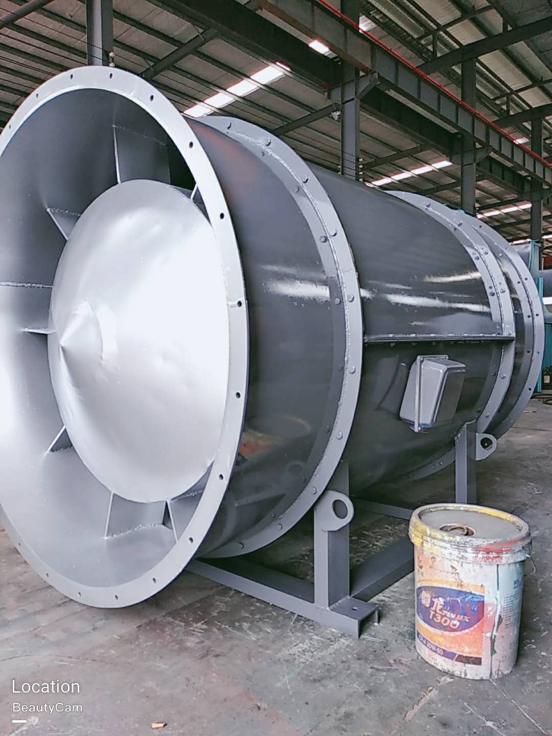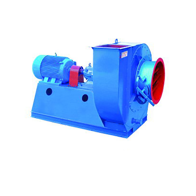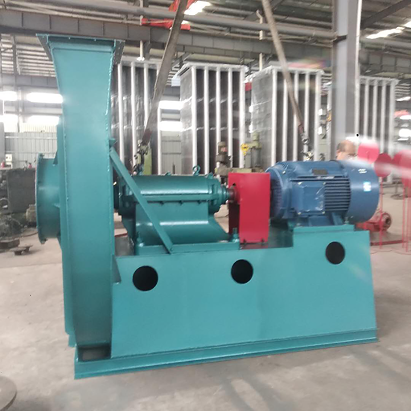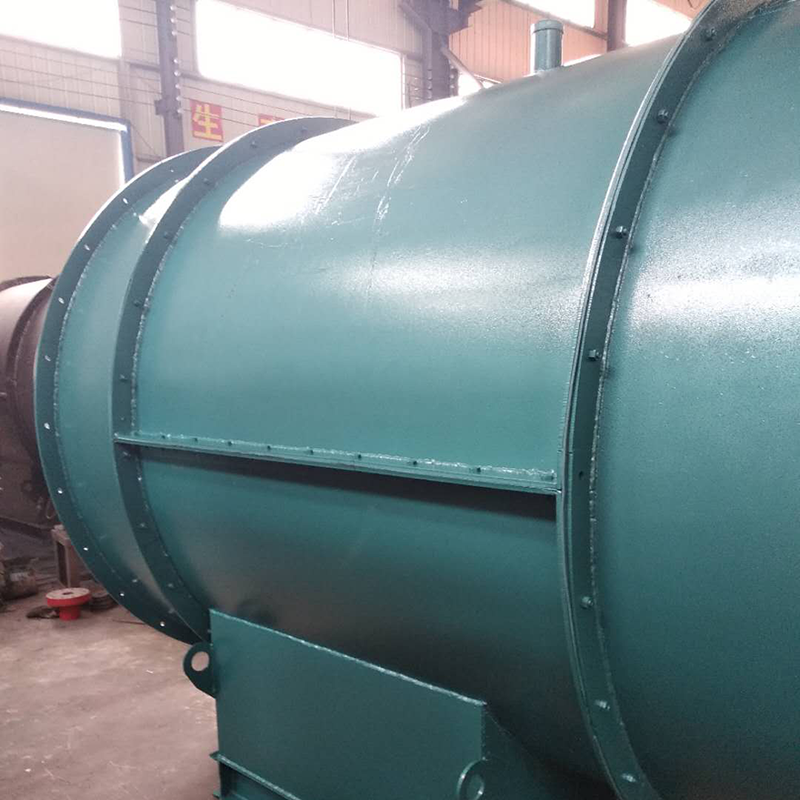
Taiyuan major Wet electrostatic precipitator Fan performance parameters. The performance parameters of fan mainly include flow, pressure, power, efficiency and speed. In addition, the size of noise and vibration is also the main fan design index. Flow, also known as air volume, is expressed by the volume of gas flowing through the fan in unit time; Pressure, also known as wind pressure, refers to the pressure rise value of gas in the fan, including static pressure, dynamic pressure and total pressure; Power refers to the input power of the fan, namely shaft power. The ratio of effective power of fan to shaft power is called efficiency. Wet electrostatic precipitator manufactor The total pressure efficiency of fan can reach 90%. Fans are widely used for ventilation, dust discharge and cooling of factories, mines, tunnels, cooling towers, vehicles, ships and buildings; Ventilation and induced draft of boiler and industrial furnace; Cooling and ventilation in air conditioning equipment and household appliances; Drying and selection of grain; Wind source of wind tunnel and inflation and propulsion of hovercraft. The working principle of the fan is basically the same as that of the turbine compressor, but because the gas flow rate is low and the pressure changes little, it is generally unnecessary to consider the change of gas specific volume, that is, treat the gas as an incompressible fluid

(2) Precautions for normal operation of fan 1. If the flow is found to be too large, which does not meet the operating requirements, or less flow is required in a short time, the throttling device can be used to adjust to meet the operating requirements. 2. The sensitivity of thermometer and oil pointer shall be checked regularly. 3. In case of any abnormal phenomenon during the start-up, shutdown or operation of the fan, it shall be checked in time. 4. For minor faults found in the inspection, find out the causes in time and try to eliminate or deal with them. If minor faults cannot be eliminated or major faults are found, repair them immediately. 5. In addition to replacing the lubricating oil during each maintenance, the lubricating oil shall also be replaced regularly. Observe the oil level at ordinary times and replenish lubricating oil in time.

In order to avoid man-made faults and accidents caused by improper maintenance, prevent the occurrence of natural faults and accidents of fans and motors in all aspects, so as to give full play to the efficiency of equipment and extend the service life of equipment, therefore, the maintenance of fans must be strengthened. (1) Working system of fan maintenance The fan maintenance personnel must pay attention to the following points: 1. The fan can only be operated when the fan equipment is completely normal. 2. If the fan equipment starts after maintenance, pay attention to whether all parts of the fan are normal. 3. Regularly clean the dust, dirt, water and other impurities inside the fan and gas transmission pipeline, and check whether the impeller is worn and rusted, if any, repair and replace it in time. 4. Regularly replace the lubricating oil (recommended 3-6 months). It is recommended to add N46 (ISO VG46, 30) in summer and N32 (ISO VG32, 20) in winter. The oil level should be at 1/2 of the oil window. 5. Regularly check (3-6 months is recommended) couplings, pulleys, etc. If parts are found to be worn or rusted, they should be repaired and replaced immediately. 6. The equipment shall not be repaired during operation.

(3) The main faults and causes of the fan may occur during the operation of the fan. For the faults generated, the causes must be quickly identified and solved in time to prevent accidents. Faults in the Operation of 4-72-12 Centrifugal Fan and the Causes Table Fault Name Causes Severe Vibration of Bearing Box 1. The fan shaft is different from the motor shaft, and the coupling is installed askew. 2. The casing or air inlet rubs with the impeller. 3. The foundation stiffness is not enough or firm. 4. Impeller rivet is loose or wheel disc is deformed. 5. The impeller shaft disk and shaft are loose, and the coupling bolt is movable. 6. The connection between casing and bracket, bearing box and bracket, bearing box and seat is loose. 7. The air inlet and outlet pipes of the fan are poorly installed, causing vibration. 8. The rotor is unbalanced. Bearing temperature rise is too high 1. The bearing box vibrates violently. 2. The lubricating grease is poor in quality, deteriorated or overfilled, or contains dust, sand, dirt and other impurities. 3. The tightening force of connecting bolts of bearing cover seat is too large or too small. 4. The shaft and rolling bearing are installed askew, and the front and rear bearings are not concentric. 5. The rolling bearing is damaged. The motor current is too high and the temperature rise is too high. 1. The throttle valve in the air inlet pipe is not closed tightly when driving. 2. The flow exceeds the specified value, or the air duct leaks. 3. The gas density conveyed by the fan is too high. 4. The input voltage of the motor is too low or the power supply is cut off individually. 5. The coupling is improperly connected, the leather ring is too tight or the gap is uneven. 6. Affected by the violent vibration of the bearing box. 7. Affected by deterioration or failure of parallel fans. When the belt slides down, the two pulleys are not in the same plane with each other. Belt runout The distance between two pulleys is too close or the belt is too long.

Selection and application of fan performance (I) Description of fan performance: 1. № 10, 12, 16, 20 are converted according to dimensionless performance of № 10 model. 2. № 5, 6, 8 are converted according to dimensionless performance of № 5 model. 3. № 5 and below shall be determined according to the performance of the measured prototype. Note: According to the dimensionless performance curve conversion formula, total pressure H=ρ u2 H (Pa) flow Q=900 π D22 uQ (m3/h) shaft power N=N × D22u3 ρ/4000 (kw), where D2 - impeller outer diameter (m) u - impeller outer edge linear speed (m/s) ρ - gas density (Kg/m3), the required power rate shall be based on shaft power plus mechanical loss and motor reserve. 4. The solid line is № 5 model, and the dotted line is № 10 model. The performance of the fan is expressed by the flow, total pressure, main shaft speed, shaft power, efficiency and other parameters of the fan, and there are certain relationships between the parameters, which are listed in the following table. The relationship of fan performance parameters changes density ρ, speed n changes speed n, atmospheric pressure P, gas temperature t Q1/Q2=n1/n2 H1/H2=(n1/n2) 2 ρ 1/ρ 2 N1/N2=(n1/n2) 3 ρ 1/ρ 2 η 1=η 2 Q1/Q2=n1/n2 H1/H2=(n1/n2) 2 (P1/P2) (273+t2/273+t1) N1/N2=(n1/n2) 3 (P1/P2) (273+t2/273+t1) η 1=η 2 Note: 1. In the middle, Q represents flow (m3/h), H represents total pressure (Pa), N represents shaft power (kw), η represents full pressure efficiency, ρ represents density (kg/m3), t represents temperature (℃), n represents speed (r/min), and P represents atmospheric pressure (Pa). 2. The footnote symbol 2 indicates the known performance and related parameters, and the footnote symbol 1 indicates the required performance and related parameters. (


