(3) The main faults and causes of the fan may occur during the operation of the fan. For the faults generated, the causes must be quickly identified and solved in time to prevent accidents. Faults in the Operation of 4-72-12 Centrifugal Fan and the Causes Table Fault Name Causes Severe Vibration of Bearing Box 1. The fan shaft is different from the motor shaft, and the coupling is installed askew. 2. The casing or air inlet rubs with the impeller. 3. The foundation stiffness is not enough or firm. 4. Impeller rivet is loose or wheel disc is deformed. 5. The impeller shaft disk and shaft are loose, and the coupling bolt is movable. 6. The connection between casing and bracket, bearing box and bracket, bearing box and seat is loose. 7. The air inlet and outlet pipes of the fan are poorly installed, causing vibration. 8. The rotor is unbalanced. Bearing temperature rise is too high 1. The bearing box vibrates violently. 2. The lubricating grease is poor in quality, deteriorated or overfilled, or contains dust, sand, dirt and other impurities. 3. The tightening force of connecting bolts of bearing cover seat is too large or too small. 4. The shaft and rolling bearing are installed askew, and the front and rear bearings are not concentric. 5. The rolling bearing is damaged. The motor current is too high and the temperature rise is too high. 1. The throttle valve in the air inlet pipe is not closed tightly when driving. 2. The flow exceeds the specified value, or the air duct leaks. 3. The gas density conveyed by the fan is too high. 4. The input voltage of the motor is too low or the power supply is cut off individually. 5. The coupling is improperly connected, the leather ring is too tight or the gap is uneven. 6. Affected by the violent vibration of the bearing box. 7. Affected by deterioration or failure of parallel fans. When the belt slides down, the two pulleys are not in the same plane with each other. Belt runout The distance between two pulleys is too close or the belt is too long.

Selection and application of fan performance (I) Description of fan performance: 1. № 10, 12, 16, 20 are converted according to dimensionless performance of № 10 model. 2. № 5, 6, 8 are converted according to dimensionless performance of № 5 model. 3. № 5 and below shall be determined according to the performance of the measured prototype. Note: According to the dimensionless performance curve conversion formula, total pressure H=ρ u2 H (Pa) flow Q=900 π D22 uQ (m3/h) shaft power N=N × D22u3 ρ/4000 (kw), where D2 - impeller outer diameter (m) u - impeller outer edge linear speed (m/s) ρ - gas density (Kg/m3), the required power rate shall be based on shaft power plus mechanical loss and motor reserve. 4. The solid line is № 5 model, and the dotted line is № 10 model. The performance of the fan is expressed by the flow, total pressure, main shaft speed, shaft power, efficiency and other parameters of the fan, and there are certain relationships between the parameters, which are listed in the following table. The relationship of fan performance parameters changes density ρ, speed n changes speed n, atmospheric pressure P, gas temperature t Q1/Q2=n1/n2 H1/H2=(n1/n2) 2 ρ 1/ρ 2 N1/N2=(n1/n2) 3 ρ 1/ρ 2 η 1=η 2 Q1/Q2=n1/n2 H1/H2=(n1/n2) 2 (P1/P2) (273+t2/273+t1) N1/N2=(n1/n2) 3 (P1/P2) (273+t2/273+t1) η 1=η 2 Note: 1. In the middle, Q represents flow (m3/h), H represents total pressure (Pa), N represents shaft power (kw), η represents full pressure efficiency, ρ represents density (kg/m3), t represents temperature (℃), n represents speed (r/min), and P represents atmospheric pressure (Pa). 2. The footnote symbol 2 indicates the known performance and related parameters, and the footnote symbol 1 indicates the required performance and related parameters. (

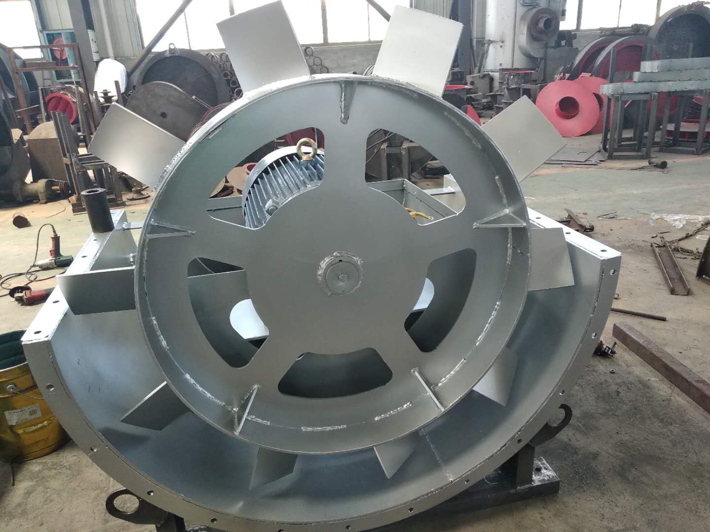
According to the report data released by the Global Wind Energy Council, the new installed capacity of global wind power in 2014 was 51477MW, up 44% year on year, and the cumulative installed capacity exceeded the threshold of 50GW for the first time. All data set new world records. China's wind power industry has driven global growth. In 2014, China's new installed capacity of wind power was 23350500 kilowatts, 45.1% higher than that of the previous year, large Axial flow fan The cumulative installed capacity has reached nearly 115 million kilowatts, of which the grid connected capacity is nearly 100 million kilowatts, accounting for 7% of the total installed power generation capacity. In addition to the strength of wind power itself, the recovery of the wind power industry has also contributed to the decline of coal prices. The decline of fuel costs has led to the profitability of most power enterprises hitting a new high in 2014, Axial flow fan manufactor This can expand the scale of wind power construction and accelerate the payment of unit arrears. As a result, the performance of wind power equipment manufacturers was in full swing in 2014, the market concentration was further improved to the top eight complete machine enterprises, and China's wind power industry basically ended the situation of low price competition. The wind power industry generally believes that the wind power industry will enter a new normal of stable growth in the future. In the next five years, the annual new installed capacity may reach at least 20 million kilowatts, and there is still a bottleneck for developers to improve their profits.

The key points of factors to be considered in the technical approach to the transformation of wet electrostatic precipitators: the wet electrostatic precipitators built before the mid-1970s could not meet the requirements of the new emission standards because of the low requirements for boiler smoke and dust emissions, the small selection of equipment capacity, the outdated structure of electrostatic precipitators, aging of dust removal equipment, low dust removal efficiency and other reasons, These electrostatic precipitators have a problem of transformation to further improve efficiency. large Axial flow fan manufactor The improvement measures for the original equipment should be considered from both technical and economic aspects, and the following technical approaches are generally adopted: 1. Discover the potential of electrostatic precipitator equipment. For example, adjust the rapping cycle and rapping force of the electrode to improve the corona power and reduce the re flying of dust; Improve the uneven distribution of flue gas velocity and readjust the technical parameters of the airflow distribution device; Adjust the control mode or power supply mode of the power supply equipment. 2、 large Axial flow fan Combination with other dedusting equipment. That is, a primary precipitator is added before or after the electrostatic precipitator. 3. Increase the capacity (or dust collection area) of the electrostatic precipitator. That is, add an electric field, or increase or widen the electric field of the electrostatic precipitator.

Before installation, first prepare the materials and tools for installation, and check the parts of the fan, especially the impeller, main shaft, bearing and other parts. If any damage is found, repair it, and then clean the inside of the bearing box with kerosene. In the process of installation, the following points must be paid attention to: 1. In order to prevent rust and reduce the difficulty of disassembly, some grease or machine oil should be coated on some joint surfaces. 2. When installing the bolts on the joint surface, if there are positioning pins, install the pins and tighten them before tightening the bolts. 3. Check that there should be no tools and sundries falling or left in the casing and other casings. Installed and used by CHANG factory bridge QIAO ISO9001 quality management system certification enterprise of Beijing No. 2 Blower Works 1. When installing the fan, the inlet and outlet must be provided with soft connection, and the weight of the gas transmission pipeline should not be added to the casing. Correct the gap size between the air inlet and the impeller according to the drawing, and keep the shaft in a horizontal position. 2. When installing the soft connection of the air inlet, the bolts of the air inlet itself can be directly used for connection. At this time, the air inlet is fixed by three countersunk screws.


