(3) The main faults and causes of the fan may occur during the operation of the fan. For the faults generated, the causes must be quickly identified and solved in time to prevent accidents. Faults in the Operation of 4-72-12 Centrifugal Fan and the Causes Table Fault Name Causes Severe Vibration of Bearing Box 1. The fan shaft is different from the motor shaft, and the coupling is installed askew. 2. The casing or air inlet rubs with the impeller. 3. The foundation stiffness is not enough or firm. 4. Impeller rivet is loose or wheel disc is deformed. 5. The impeller shaft disk and shaft are loose, and the coupling bolt is movable. 6. The connection between casing and bracket, bearing box and bracket, bearing box and seat is loose. 7. The air inlet and outlet pipes of the fan are poorly installed, causing vibration. 8. The rotor is unbalanced. Bearing temperature rise is too high 1. The bearing box vibrates violently. 2. The lubricating grease is poor in quality, deteriorated or overfilled, or contains dust, sand, dirt and other impurities. 3. The tightening force of connecting bolts of bearing cover seat is too large or too small. 4. The shaft and rolling bearing are installed askew, and the front and rear bearings are not concentric. 5. The rolling bearing is damaged. The motor current is too high and the temperature rise is too high. 1. The throttle valve in the air inlet pipe is not closed tightly when driving. 2. The flow exceeds the specified value, or the air duct leaks. 3. The gas density conveyed by the fan is too high. 4. The input voltage of the motor is too low or the power supply is cut off individually. 5. The coupling is improperly connected, the leather ring is too tight or the gap is uneven. 6. Affected by the violent vibration of the bearing box. 7. Affected by deterioration or failure of parallel fans. When the belt slides down, the two pulleys are not in the same plane with each other. Belt runout The distance between two pulleys is too close or the belt is too long.

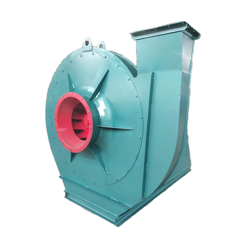
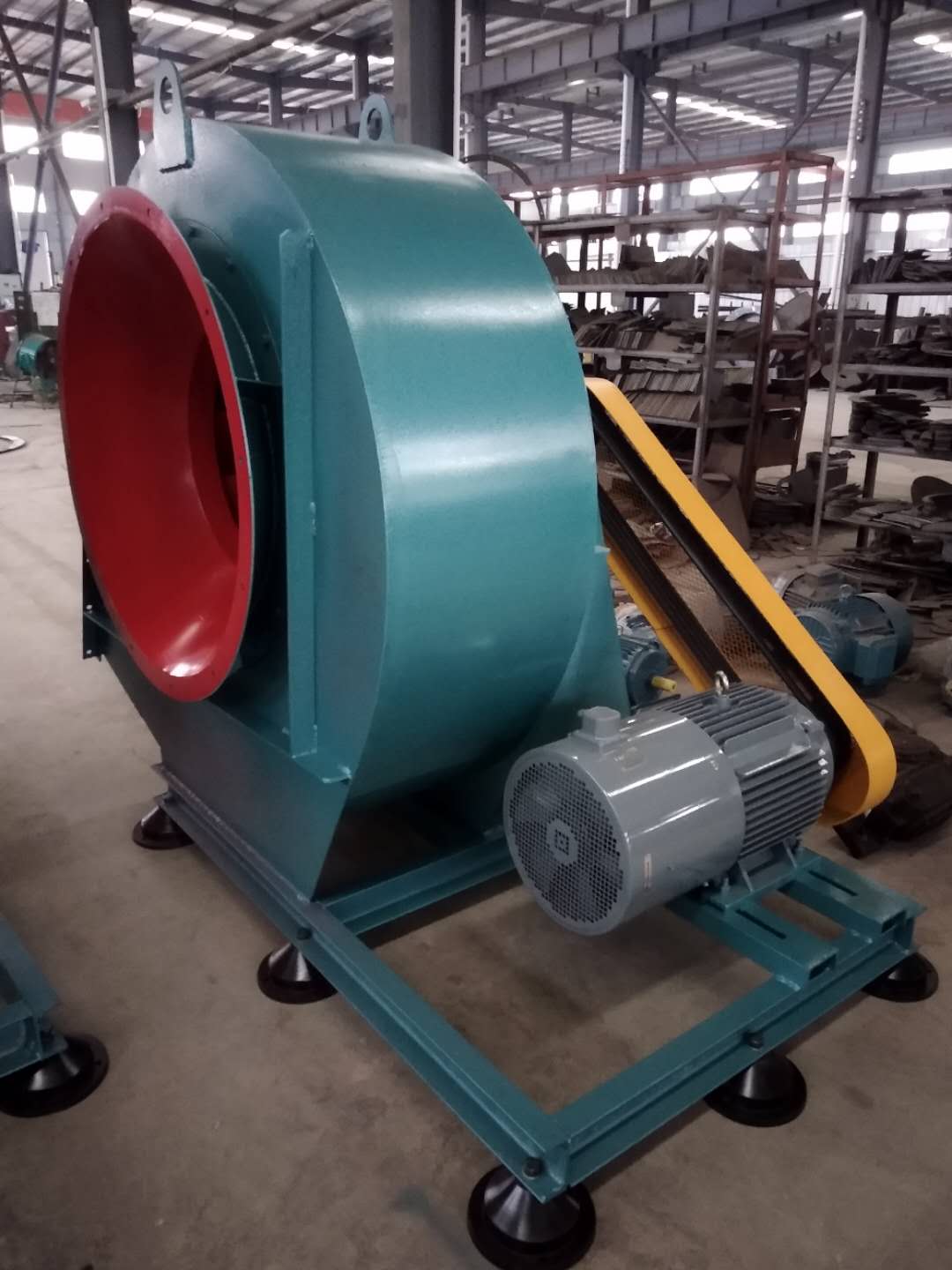
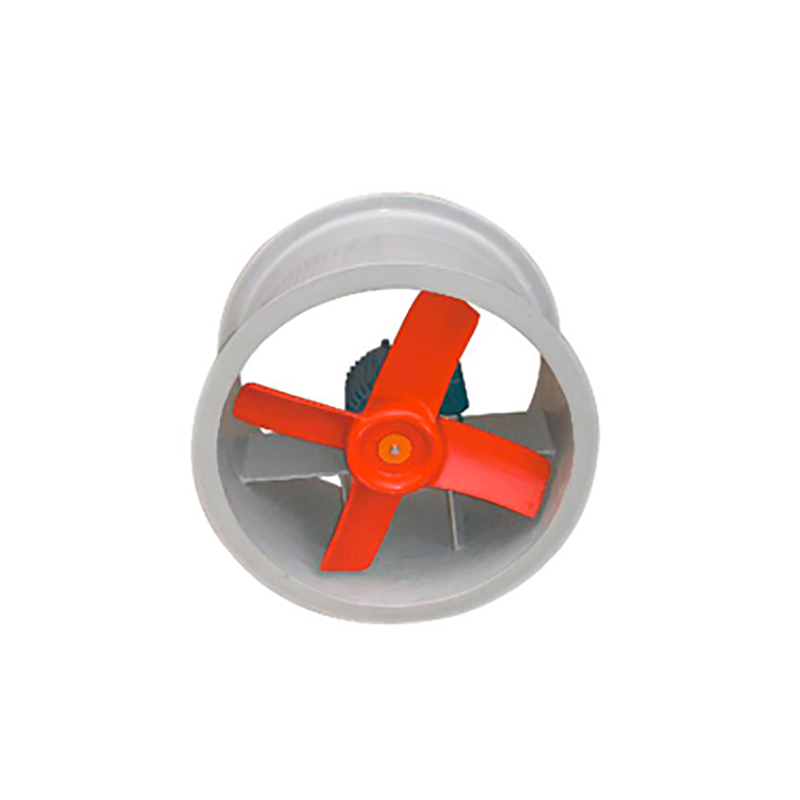
large Centrifugal fan Fans can be divided into axial flow fans, centrifugal fans and diagonal flow (mixed flow) fans according to the flow direction after the airflow enters the impeller. Fans are divided into press in local fans (hereinafter referred to as press in fans) and flame-proof motors placed outside or inside the flow channel, and flame-proof motors placed inside the explosion-proof sealing chamber of the extraction type local fans (hereinafter referred to as extraction fans) according to their purposes. Centrifugal fan manufactor Fans can also be divided into single-stage, two-stage or multi-stage pressurization fans according to the form of pressurization. For example, 4-72 is single-stage pressurization, and high-end fan is multi-stage pressurization fan. Fans can be divided into axial flow fans, mixed flow fans, roof fans, air conditioning fans, etc. Fan can be divided into negative pressure fan, low pressure fan, medium pressure fan and high pressure fan according to pressure. According to the outlet pressure (pressure rise), it can be divided into: ventilator (≤ 15000 Pa), blower (15-350000 Pa), compressor (≥ 350000 Pa)

Selection and application of fan performance (I) Description of fan performance: 1. № 10, 12, 16, 20 are converted according to dimensionless performance of № 10 model. 2. № 5, 6, 8 are converted according to dimensionless performance of № 5 model. 3. № 5 and below shall be determined according to the performance of the measured prototype. Note: According to the dimensionless performance curve conversion formula, total pressure H=ρ u2 H (Pa) flow Q=900 π D22 uQ (m3/h) shaft power N=N × D22u3 ρ/4000 (kw), where D2 - impeller outer diameter (m) u - impeller outer edge linear speed (m/s) ρ - gas density (Kg/m3), the required power rate shall be based on shaft power plus mechanical loss and motor reserve. 4. The solid line is № 5 model, and the dotted line is № 10 model. The performance of the fan is expressed by the flow, total pressure, main shaft speed, shaft power, efficiency and other parameters of the fan, and there are certain relationships between the parameters, which are listed in the following table. The relationship of fan performance parameters changes density ρ, speed n changes speed n, atmospheric pressure P, gas temperature t Q1/Q2=n1/n2 H1/H2=(n1/n2) 2 ρ 1/ρ 2 N1/N2=(n1/n2) 3 ρ 1/ρ 2 η 1=η 2 Q1/Q2=n1/n2 H1/H2=(n1/n2) 2 (P1/P2) (273+t2/273+t1) N1/N2=(n1/n2) 3 (P1/P2) (273+t2/273+t1) η 1=η 2 Note: 1. In the middle, Q represents flow (m3/h), H represents total pressure (Pa), N represents shaft power (kw), η represents full pressure efficiency, ρ represents density (kg/m3), t represents temperature (℃), n represents speed (r/min), and P represents atmospheric pressure (Pa). 2. The footnote symbol 2 indicates the known performance and related parameters, and the footnote symbol 1 indicates the required performance and related parameters. (

Centrifugal fan manufactor Forecast from the characteristics of fan demand. large Centrifugal fan For small and medium-sized fans with large usage and wide range, the product structure and manufacturing process are relatively simple, and the cost is also low. Users mainly pursue high efficiency, low noise, long life, and low price. The other is capital and technology intensive. The product structure is complex, the manufacturing cycle is long, and the completeness and systematicness are also strong. Moreover, it operates under high pressure, high temperature and high speed conditions, and some even operate under severe conditions. Users have different requirements for this type of fan. For turbine blowers, compressors and large ventilators, users mainly pursue high quality, high reliability, smooth operation and long cycle


