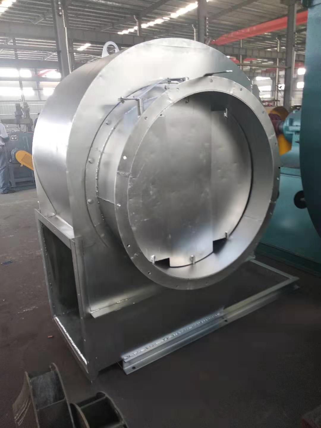
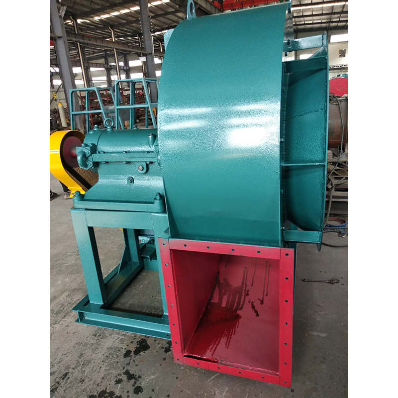
3. When installing Type C and Type B, ensure that the two pulley positions are on the same plane, and the flatness tolerance is 0.5mm. 4. When installing Type D, use a dial indicator and feeler gauge to measure the coaxiality of the fan spindle and motor spindle and the parallelism of both ends of the coupling. The coaxiality tolerance of two shafts is 0.2mm, the parallelism tolerance of both ends of the coupling is 0.2mm, and the spacing between two planes of the coupling is 5 to 8mm. 5. After the fan is installed, move the rotor with hand or lever to check whether it is too tight or collided. The test run can be carried out without overtightening or collision. 6. After the motor is installed, the belt pulley or coupling guard shall be installed. If the air inlet is not connected to the air inlet pipe, the guard net or other safety devices (provided by the user) shall also be provided. 7. Other parts shall be installed according to the corresponding positions in the drawing. 8. Add N46 (ISO VG46, 30) in summer and N32 (ISO VG32, 20) in winter. The oil level should be at 1/2 of the oil window.
Selection and application of fan performance (I) Description of fan performance: 1. № 10, 12, 16, 20 are converted according to dimensionless performance of № 10 model. 2. № 5, 6, 8 are converted according to dimensionless performance of № 5 model. 3. № 5 and below shall be determined according to the performance of the measured prototype. Note: According to the dimensionless performance curve conversion formula, total pressure H=ρ u2 H (Pa) flow Q=900 π D22 uQ (m3/h) shaft power N=N × D22u3 ρ/4000 (kw), where D2 - impeller outer diameter (m) u - impeller outer edge linear speed (m/s) ρ - gas density (Kg/m3), the required power rate shall be based on shaft power plus mechanical loss and motor reserve. 4. The solid line is № 5 model, and the dotted line is № 10 model. The performance of the fan is expressed by the flow, total pressure, main shaft speed, shaft power, efficiency and other parameters of the fan, and there are certain relationships between the parameters, which are listed in the following table. The relationship of fan performance parameters changes density ρ, speed n changes speed n, atmospheric pressure P, gas temperature t Q1/Q2=n1/n2 H1/H2=(n1/n2) 2 ρ 1/ρ 2 N1/N2=(n1/n2) 3 ρ 1/ρ 2 η 1=η 2 Q1/Q2=n1/n2 H1/H2=(n1/n2) 2 (P1/P2) (273+t2/273+t1) N1/N2=(n1/n2) 3 (P1/P2) (273+t2/273+t1) η 1=η 2 Note: 1. In the middle, Q represents flow (m3/h), H represents total pressure (Pa), N represents shaft power (kw), η represents full pressure efficiency, ρ represents density (kg/m3), t represents temperature (℃), n represents speed (r/min), and P represents atmospheric pressure (Pa). 2. The footnote symbol 2 indicates the known performance and related parameters, and the footnote symbol 1 indicates the required performance and related parameters. (
Emergency stop: major Axial flow fan manufactor In case of one of the following situations during the unit commissioning, emergency shutdown shall be carried out immediately. The emergency stop operation is to press the stop button of the main motor, and then carry out the remedial work after the shutdown; The centrifugal fan suddenly vibrates strongly and has exceeded the trip value; There is scratch or abnormal friction sound inside the machine body; major Axial flow fan Smoke occurs at any bearing or seal, or the temperature of a bearing rises sharply to the alarm value; When the oil pressure is lower than the alarm value and cannot be restored to normal; The liquid level in the oil tank is low, and there is suction phenomenon; When the axial displacement value increases significantly and reaches the alarm value;
Correct maintenance is an important guarantee for the safe and reliable operation of the fan and the improvement of its service life. Therefore, Axial flow fan manufactor When using fans, full attention must be paid. Impeller maintenance: at the initial stage of impeller operation and during all regular inspections, whenever there is an opportunity, the impeller must be checked for cracks, wear, dust and other defects. The impeller must be kept clean whenever possible, major Axial flow fan The steel wire brush shall be used regularly to remove the dust and rust on the impeller. As the travel time increases, the dust can not be evenly attached to the impeller, which will cause damage to the balance of the impeller and even cause rotor vibration. As long as the impeller is repaired, it needs to be dynamically balanced again. If possible, the portable trial dynamic balancing instrument can be used for on-site balancing. Before dynamic balancing, check whether all fastening bolts are tightened. Since the impeller has been operating in an unbalanced state for a period of time, these bolts may have become loose. Bearing maintenance: frequently check the oil supply of bearing lubricating oil. If the box leaks oil, tighten the bolts of the end cover a little. If this is not enough, you may have to use new sealing packing. When the bearing lubricating oil is in normal use, it should be replaced at least once every six months. When it is used for the first time, it should be done after 200 hours of operation. The second oil change should be done in 1 to 2 months. After that, the lubricating oil should be checked once a week. If the lubricating oil does not deteriorate, the oil change can be extended to 2 to 4 months. The specified brand of lubricating oil (specified on the general drawing) must be used when replacing, The old oil in the oil tank shall be completely drained and cleaned before new oil can be filled. If the fan bearing needs to be replaced, pay attention to the following matters: before installing the new bearing, the bearing and bearing box must be very clean. Place the bearing in the oil with a temperature of about 70~80 ℃ and heat it before installing it on the shaft. Do not force assembly to avoid damaging the shaft. Maintenance of other supporting equipment: see the respective user manual for the maintenance of various supporting equipment, including motors, electric actuators, instruments, meters, etc. These operating instructions are provided by each supporting manufacturer. The manufacturer will pack these instructions together and provide them to the user
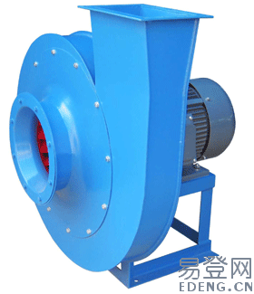
Forecast the demand structure from the main fields. major Axial flow fan General ventilation fans (generally small and medium-sized centrifugal and axial fans) are the most widely used, with the largest demand and the largest number of manufacturers. In general, the supply of such products exceeds the demand. Although the demand for special purpose fans (including anti-corrosion fans, high-temperature fans, wear-resistant fans, fire smoke exhaust fans, etc.) is not large, due to the special operating environment, they need to be treated differently, because the main material requirements are special. The biggest feature of Roots blower is that when the pressure is adjusted within the allowable range, the flow changes little, the pressure selection range is wide, and it has the characteristics of forced gas transmission. The main disadvantage is that the noise is large. Axial flow fan manufactor Through technology introduction, joint venture and self-development, China has launched a three blade roots blower with low noise, which is very popular with users and has a good market prospect. Turbine compressor (including centrifugal compressor, axial compressor and axial centrifugal compound compressor) is an important equipment of major engineering complete equipment, which plays an important role in the national economy. The performance of turbine compressor requires high pressure and large flow. With the large-scale of the complete set of equipment, the turbine compressor parameters are required to be higher and higher. Such as blast furnace smelting plant, large coal chemical plant, large fertilizer plant, large ethylene plant, large air separation plant, natural gas pipeline transportation plant and oil field gas injection plant. The demand for such products accounts for a small proportion of the total fan volume, but because of their importance, complex structure, long manufacturing cycle and high technical content, they have relatively good economic and social benefits. Turbine compressor manufacturing level represents the overall level of the fan industry


