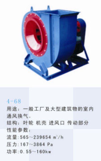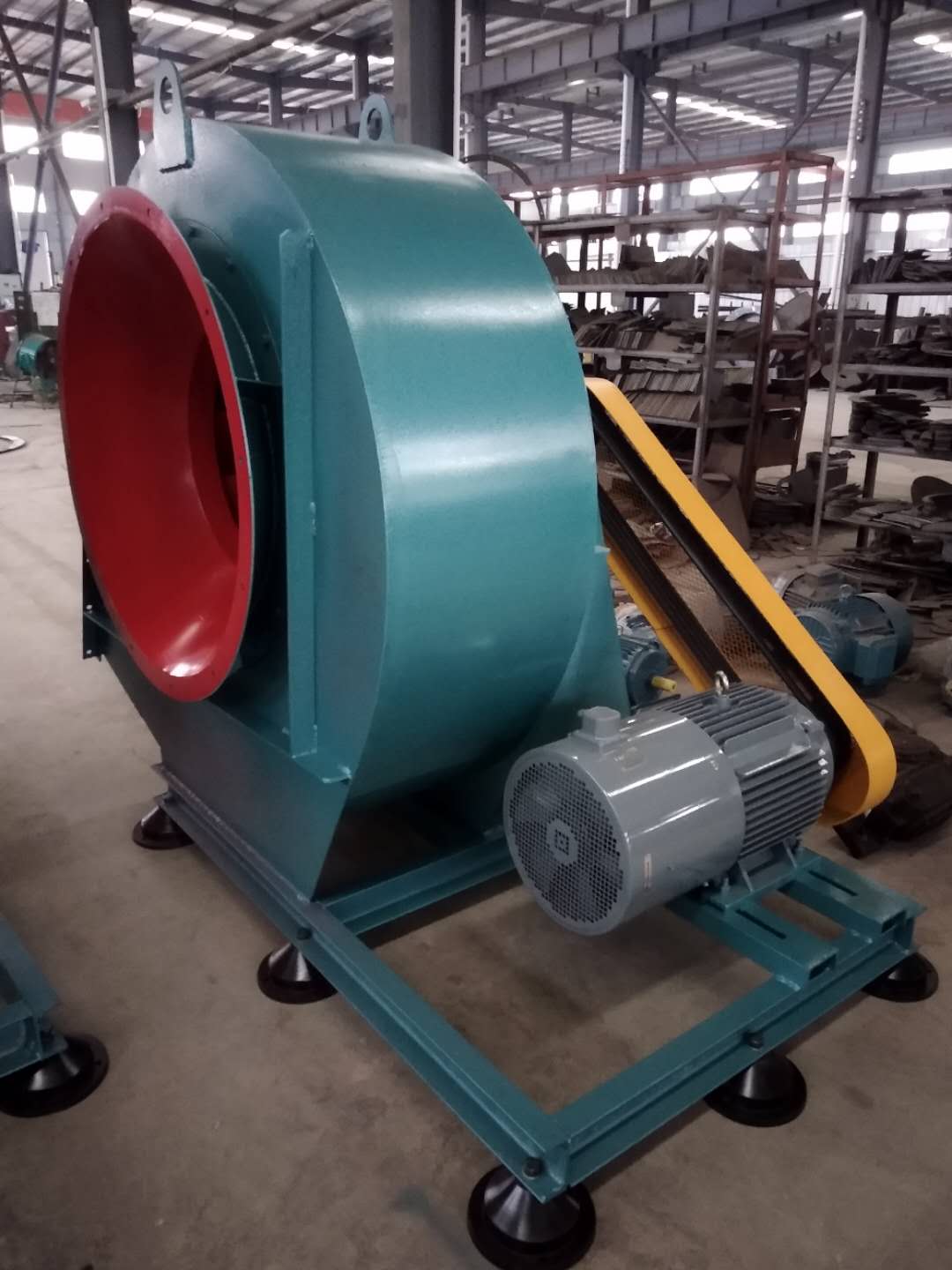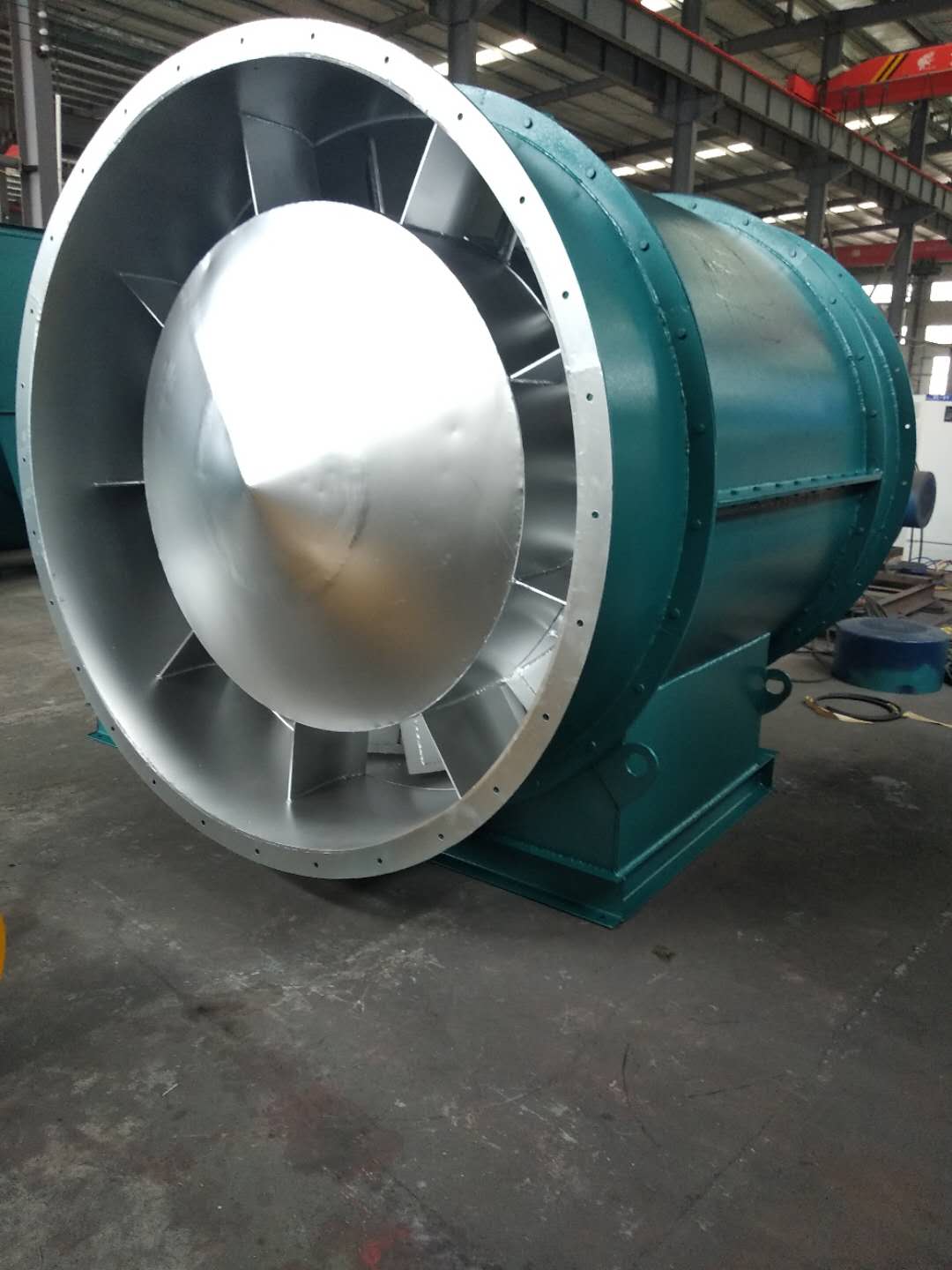
Gas compression and gas transmission machinery is a machine that converts rotating mechanical energy into gas pressure energy and kinetic energy and transports gas. The main structural components of the fan are impeller, casing, air inlet, support, motor, pulley, coupling, silencer, transmission parts (bearings), etc. customized FRP fan The unpowered fan uses the air thermal convection caused by the natural wind force and the indoor and outdoor temperature difference to drive the turbine to rotate, thus using the centrifugal force and negative pressure effect to exhaust the indoor stale hot air. Jiujiang FRP fan company The fan is related to the transmission and distribution energy consumption of the system, and is a very critical part of building energy conservation. According to the fan inspection conducted by the National Air Conditioning Equipment Quality Supervision and Inspection Center for many years, many fans have problems under rated conditions, so it is necessary to produce and manufacture fans in strict accordance with product standards. customized FRP fan At the beginning of the fan operation, the vibration of the bearing is very small, but with the extension of the operating time, the dust in the fan will be unevenly attached to the impeller, gradually destroying the dynamic balance of the fan, making the bearing vibration gradually increase. Once the vibration reaches the maximum allowable value of 11mm/s of the fan (the maximum allowable value expressed by the amplitude value is as follows), The fan must be shut down for repair (dust accumulation shall be removed and dynamic balance shall be redone). Because it is very dangerous at this time, users must not use it forcibly. When the fan vibration is close to the dangerous value, the vibration measuring instrument will give an alarm.

FRP fan company The work starts before the fan is used. one Jiujiang FRP fan company Carefully read the fan operation instructions and product samples, and be familiar with and understand the fan specifications, forms, impeller rotation direction and air flow in and out direction; Check whether all parts of the fan are in good condition again, or they can be installed and used only after being repaired. 2. The fan must be installed with safety devices to prevent accidents, and installed and wired by professionals familiar with relevant safety requirements. 3. The air duct connecting the inlet and outlet of the fan has separate support, and it is not allowed to add the overlapping weight of the duct to the components of the fan; When installing the fan, pay attention to the horizontal position of the fan, and adjust the connection between the joint surface of the fan and the foundation and the air outlet pipe to make it coincide naturally. Forced connection is not allowed. four customized FRP fan After the fan is installed, move the impeller by hand or lever to check whether it is too tight or rubbed, and whether there is any object that hinders the rotation. The test run can be carried out only when there is no abnormal phenomenon. The exposed part of the fan transmission device should be equipped with a protective cover (provided by the user). If the fan inlet is not connected, a protective screen or other installation device (provided by the user) should also be added. 5. The power distribution control box of the fan must match the corresponding fan (power, voltage, pneumatic mode, control mode, etc.). 6. The fan wiring should be made by a professional electrician, and the wiring must be correct and reliable. Especially, the wiring number at the electric control box should be consistent with the number on the fan terminal. The fan shell should be reliably grounded. The grounding must be reliable, and zero connection cannot be used instead of grounding. 7. After all fans are installed, check whether there are any left tool box sundries inside the fan

Jiujiang customized FRP fan Installation requirements a. The foundation of the fan shall be level and solid, and the foundation height shall be ≥ 200mm. b、 The fan and air duct shall be connected by flexible hose (flexible material and non combustible), the length shall not be less than 200mm, and the pipe diameter shall be the same as the inlet and outlet size of the fan. In order to ensure that the hose will not be twisted or deformed during the system operation, it should be installed with appropriate tightness. The canvas hose installed at the suction end of the fan can be slightly tightened to prevent the fan from being sucked in during operation and reduce the sectional size of the canvas hose. c、 FRP fan company The steel support of the fan must be fixed on the concrete foundation, and a rubber damping pad must be added between the steel support of the fan and the foundation. All fan and motor components are installed on the whole steel support, and the steel ground frame is installed on the damping pad at the top of the foundation. The damping pad is preferably made of perforated rubber plates. d、 The pipe diameter at the outlet of the fan can only be increased, but not decreased. At the end of the outlet, an insect screen should be installed. When the fan is inclined to the upper outlet, a rain cap should be added

(3) The main faults and causes of the fan may occur during the operation of the fan. For the faults generated, the causes must be quickly identified and solved in time to prevent accidents. Faults in the Operation of 4-72-12 Centrifugal Fan and the Causes Table Fault Name Causes Severe Vibration of Bearing Box 1. The fan shaft is different from the motor shaft, and the coupling is installed askew. 2. The casing or air inlet rubs with the impeller. 3. The foundation stiffness is not enough or firm. 4. Impeller rivet is loose or wheel disc is deformed. 5. The impeller shaft disk and shaft are loose, and the coupling bolt is movable. 6. The connection between casing and bracket, bearing box and bracket, bearing box and seat is loose. 7. The air inlet and outlet pipes of the fan are poorly installed, causing vibration. 8. The rotor is unbalanced. Bearing temperature rise is too high 1. The bearing box vibrates violently. 2. The lubricating grease is poor in quality, deteriorated or overfilled, or contains dust, sand, dirt and other impurities. 3. The tightening force of connecting bolts of bearing cover seat is too large or too small. 4. The shaft and rolling bearing are installed askew, and the front and rear bearings are not concentric. 5. The rolling bearing is damaged. The motor current is too high and the temperature rise is too high. 1. The throttle valve in the air inlet pipe is not closed tightly when driving. 2. The flow exceeds the specified value, or the air duct leaks. 3. The gas density conveyed by the fan is too high. 4. The input voltage of the motor is too low or the power supply is cut off individually. 5. The coupling is improperly connected, the leather ring is too tight or the gap is uneven. 6. Affected by the violent vibration of the bearing box. 7. Affected by deterioration or failure of parallel fans. When the belt slides down, the two pulleys are not in the same plane with each other. Belt runout The distance between two pulleys is too close or the belt is too long.


