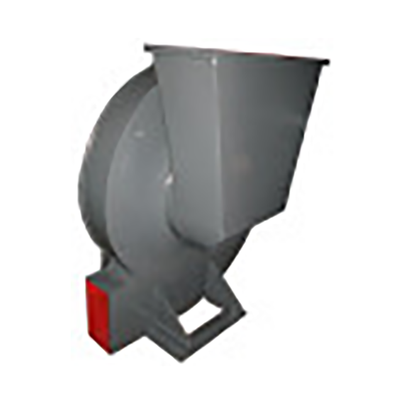
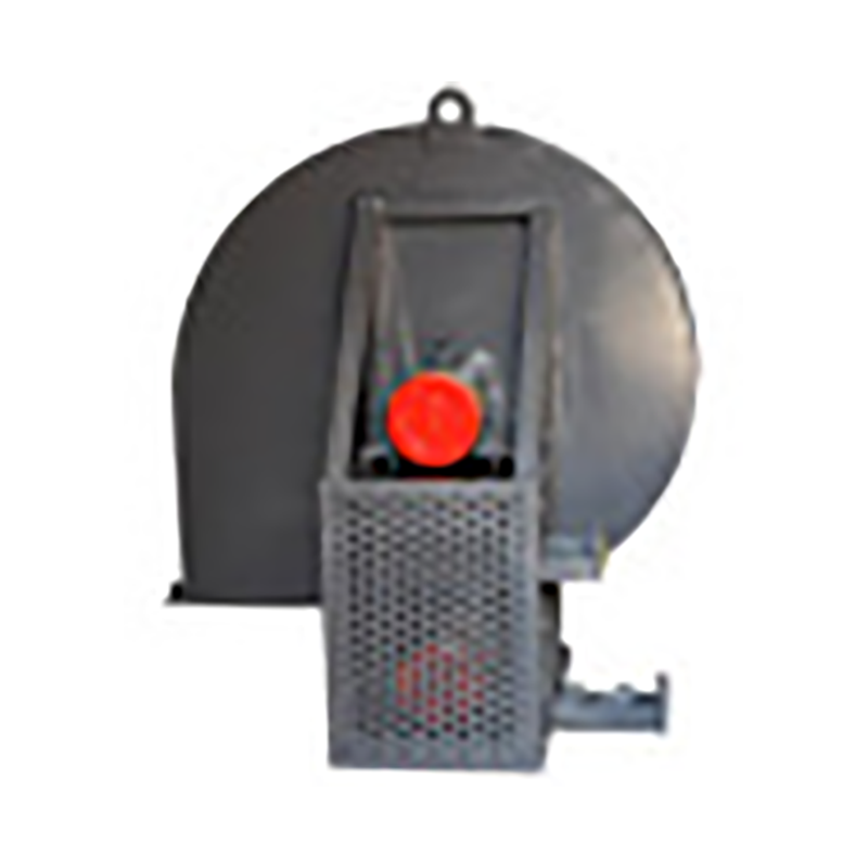
Luzhou Wet electrostatic precipitator Classified by layers. There are many classification methods for fans, which can be roughly classified according to the following levels: (1) According to the level of pressure generated, they can be divided into: volumetric: reciprocating and rotary; Turbine type: centrifugal, axial flow, mixed flow and cross flow, jet type. Fan generally refers to turbine type, namely centrifugal, axial, mixed flow, cross flow and other forms. Its main characteristics are: centrifugal fan: higher pressure, but smaller air volume. Axial flow fan: higher air volume, but lower pressure. Mixed flow fan: the air volume and pressure are between centrifugal fan and axial fan. Horizontal fan: with high dynamic pressure, it can obtain flat airflow. (2) major Wet electrostatic precipitator According to the different materials used, it can be divided into:; Iron shell fan (ordinary fan), glass fiber reinforced plastic fan, plastic fan, aluminum fan, stainless steel fan, etc. (3) According to the direction of gas flow, it can be divided into centrifugal type, axial flow type, diagonal flow type (mixed flow type) and cross flow type. (4) According to the flow direction of the airflow entering the impeller, it can be divided into axial flow fan, centrifugal fan and diagonal flow (mixed flow) fan. (5) Wet electrostatic precipitator company It can be divided into: press in local fans and flame-proof motors placed outside or inside the flow channel, and flame-proof motors placed inside the explosion-proof sealing chamber of the extraction type local fans. (6) According to the form of pressurization, it can also be divided into single-stage, two-stage or multi-stage pressurization fans
The wet electrostatic precipitator is a new kind of dust removal equipment used to treat micro dust and micro particles, major Wet electrostatic precipitator It is mainly used to remove dust, acid mist, water droplets, aerosols, odor, PM2.5 and other harmful substances in humid gases, and is an ideal equipment for controlling atmospheric dust pollution. The wet electrostatic precipitator is usually referred to as WESP, which has the same basic principle as the dry electrostatic precipitator. It goes through three stages: charging, collection and dust removal. The principle of wet electrostatic precipitator is the same as that of dry electrostatic precipitator, Luzhou Wet electrostatic precipitator The dust is charged by high-voltage corona discharge, and the charged dust reaches the dust collecting plate/tube under the action of electric field force. The dry electrostatic precipitator mainly deals with dry gas with very low water content, while the wet electrostatic precipitator mainly deals with wet gas with high water content or even saturation. There is a big difference between WESP and DESP in the way of removing the dust collected on the dust collecting plate/pipe. The dry electrostatic precipitator generally uses mechanical rapping or acoustic cleaning to remove the dust on the electrode, while the wet electrostatic precipitator uses regular flushing to remove the dust along with the flow of flushing fluid
Wet dust remover is a device that uses the action of water or other liquids and dusty gases to remove dust particles. When dust particles meet with sprayed water droplets, water films or wetted walls and devices The process of wetting, condensation, diffusion and sedimentation takes place, so it is separated from the gas to purify the gas. Luzhou Wet electrostatic precipitator company It is characterized by purifying dust at the same time It can also purify gas, major Wet electrostatic precipitator When the flue gas contains combustible components, the use of wet dust collectors can avoid equipment explosion, and the dust removal effect can generally meet the environmental protection requirements. The equipment is small and the investment is relatively low. Therefore, there are three wet dust collectors used in dust removal projects in mining, metallurgy, machinery, light industry, building materials and other industries. Sludge containing sewage must be treated, otherwise secondary pollution may occur, Therefore, it is not widely used as dry dust collector. There are many types of wet dust collectors. According to their structures, there are the following types: ① gravity spray wet dust collectors - spray scrubbing towers; ② Cyclone wet dust collector - cyclone water film dust collector, water film dust collector; ③ Self excited wet dust collector - impulse dust collector, water bath dust collector; ④ Packed wet dust collector - packed tower, turbulent ball tower; ⑤ Foam wet dust collector - foam dust collector Cyclone dust collector, leaky plate tower; ⑥ Venturi wet dust collector - Venturi tube dust collector; ⑦ Mechanical induction wet dust collector - water wheel dust collector.
Selection and application of fan performance (I) Description of fan performance: 1. № 10, 12, 16, 20 are converted according to dimensionless performance of № 10 model. 2. № 5, 6, 8 are converted according to dimensionless performance of № 5 model. 3. № 5 and below shall be determined according to the performance of the measured prototype. Note: According to the dimensionless performance curve conversion formula, total pressure H=ρ u2 H (Pa) flow Q=900 π D22 uQ (m3/h) shaft power N=N × D22u3 ρ/4000 (kw), where D2 - impeller outer diameter (m) u - impeller outer edge linear speed (m/s) ρ - gas density (Kg/m3), the required power rate shall be based on shaft power plus mechanical loss and motor reserve. 4. The solid line is № 5 model, and the dotted line is № 10 model. The performance of the fan is expressed by the flow, total pressure, main shaft speed, shaft power, efficiency and other parameters of the fan, and there are certain relationships between the parameters, which are listed in the following table. The relationship of fan performance parameters changes density ρ, speed n changes speed n, atmospheric pressure P, gas temperature t Q1/Q2=n1/n2 H1/H2=(n1/n2) 2 ρ 1/ρ 2 N1/N2=(n1/n2) 3 ρ 1/ρ 2 η 1=η 2 Q1/Q2=n1/n2 H1/H2=(n1/n2) 2 (P1/P2) (273+t2/273+t1) N1/N2=(n1/n2) 3 (P1/P2) (273+t2/273+t1) η 1=η 2 Note: 1. In the middle, Q represents flow (m3/h), H represents total pressure (Pa), N Represents shaft power (kw), η represents total pressure efficiency, ρ represents density (kg/m3), t represents temperature (℃), n represents speed (r/min), and P represents atmospheric pressure (Pa). 2. The footnote symbol 2 indicates the known performance and related parameters, and the footnote symbol 1 indicates the required performance and related parameters. (


