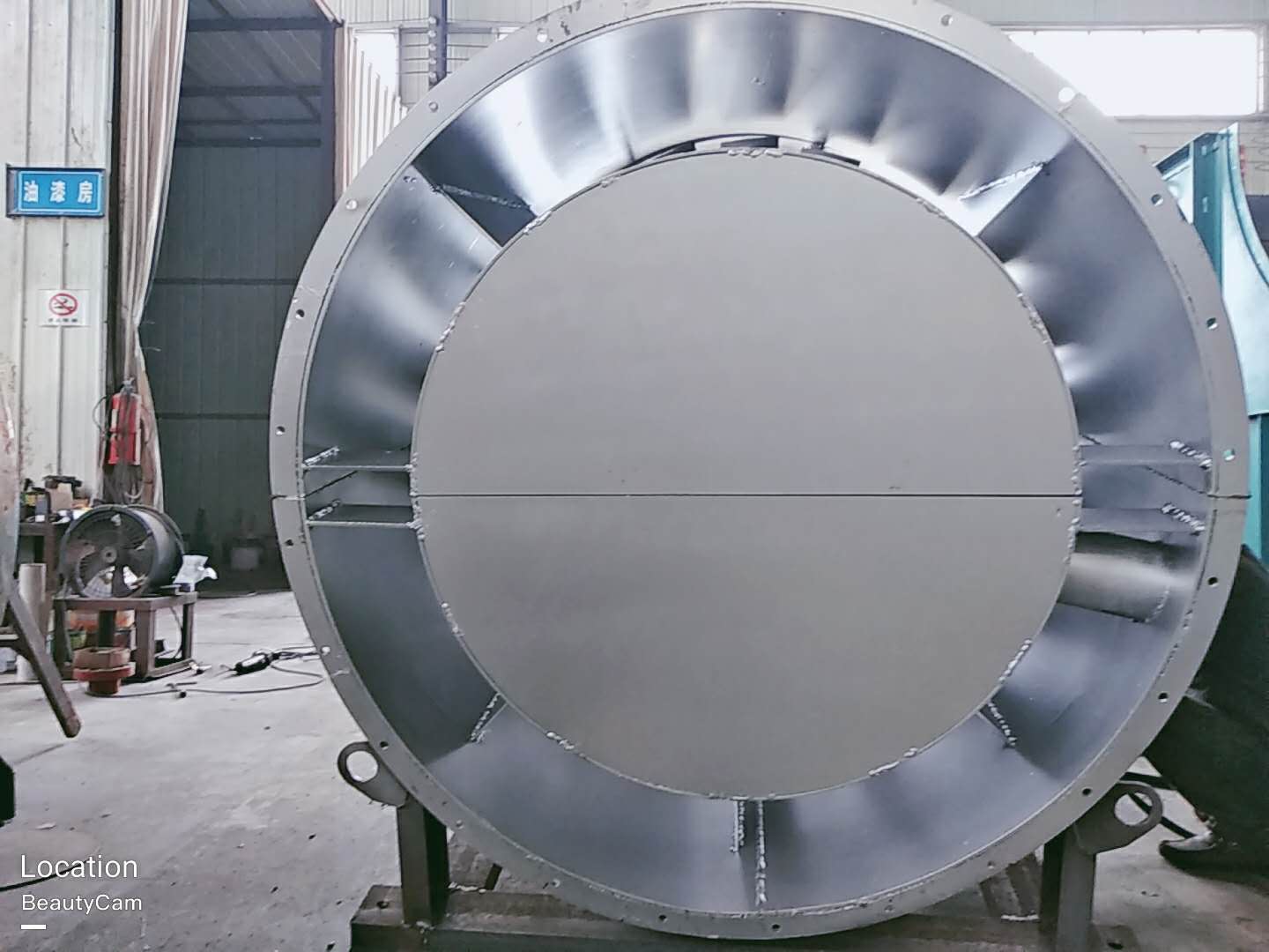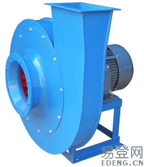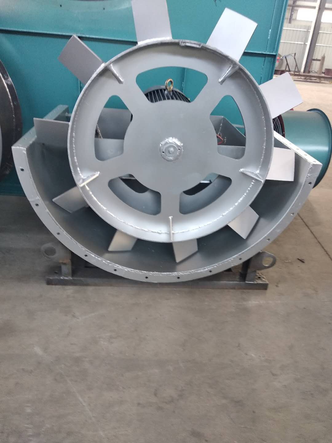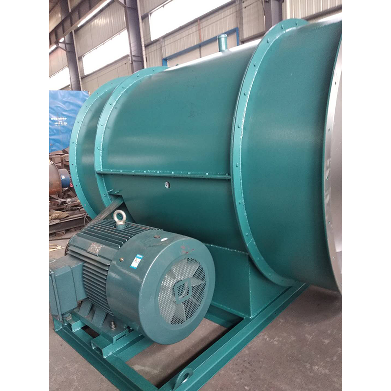
large Centrifugal fan The wet electrostatic precipitator mainly has two structural forms. One is to use corrosion-resistant conductive materials (which can be non-metallic materials with excellent conductivity or metal materials with corrosion-resistant characteristics) as the dust collector, and the other is to use non-conductive non-metallic materials as the dust collector by forming a conductive water film through water spray or overflow. Wet electrostatic precipitators can also be divided into cross flow type (horizontal) and vertical flow type (vertical) according to the flow direction of waste gas. The cross flow type is mostly plate structure, Liling Centrifugal fan The gas flows in and out in the horizontal direction, and the structure is similar to the dry electrostatic precipitator; The vertical flow type is mostly tubular structure, and the gas flow direction is vertical. Generally speaking, the efficiency of vertical flow wet electrostatic precipitator is twice as high as that of cross flow wet electrostatic precipitator under the condition of the same ventilation cross-sectional area. The dust deposited on the electrode plate can be washed down by water. Wet dust removal can avoid the re flying of captured dust and achieve high dust removal efficiency. Since there is no rapping device, the operation is also more reliable. The device that forms conductive film on the surface of the dust collector by means of water spray or overflow water has problems of corrosion, sludge and sewage treatment. It is only used when the dust concentration of the gas is low and the dust removal efficiency is required to be high; The wet electrostatic precipitator using corrosion-resistant conductive materials as dust collector does not need long-term water spraying or overflow water, Centrifugal fan manufactor Regular flushing is only carried out according to the operating conditions of the system, and only a small amount of water is consumed. This part of water can be recycled, and the dust collection system is basically free of secondary pollution.

large Centrifugal fan Common fault: the working medium of the fan in the cement industry often contains a certain amount of homogeneous particles with different sizes and shapes, such as the induced draft fan of the dust removal system and the blower for pneumatic conveying. Because these fans work in the dusty air flow, the dust particles in the air flow will not only wear the fan, but also attach ash on the fan blades, and the wear and ash deposition are uneven. As a result, the balance of the fan rotor is destroyed, which causes the fan vibration and shortens the life of the fan. In serious cases, the fan can not work normally. In particular, the fan blades are most severely worn, Centrifugal fan manufactor It not only destroys the flow characteristics in the fan, but also easily leads to major accidents such as blade fracture and runaway. The wear of transmission parts is also a common problem of fans, including various shafts, rollers, reducers, motors, pumps and other bearing positions, bearing seats, keyways, threads and other parts. The traditional repair welding machine processing method is easy to cause material damage, resulting in deformation or fracture of parts, with greater limitations; Brush plating and spray re machining methods often require outsourcing, which not only requires long repair cycle and high cost, but also can not fundamentally solve the causes of wear (poor impact resistance and yield of metal) because the repair materials are metal materials; Many parts can only be scrapped and replaced, which greatly increases the production cost and inventory of spare parts, leaving the enterprise's good resource advantage idle and wasted

Selection and application of fan performance (I) Description of fan performance: 1. № 10, 12, 16, 20 are converted according to dimensionless performance of № 10 model. 2. № 5, 6, 8 are converted according to dimensionless performance of № 5 model. 3. № 5 and below shall be determined according to the performance of the measured prototype. Note: According to the dimensionless performance curve conversion formula, total pressure H=ρ u2 H (Pa) flow Q=900 π D22 uQ (m3/h) shaft power N=N × D22u3 ρ/4000 (kw), where D2 - impeller outer diameter (m) u - impeller outer edge linear speed (m/s) ρ - gas density (Kg/m3), the required power rate shall be based on shaft power plus mechanical loss and motor reserve. 4. The solid line is № 5 model, and the dotted line is № 10 model. The performance of the fan is expressed by the flow, total pressure, main shaft speed, shaft power, efficiency and other parameters of the fan, and there are certain relationships between the parameters, which are listed in the following table. The relationship of fan performance parameters changes density ρ, speed n changes speed n, atmospheric pressure P, gas temperature t Q1/Q2=n1/n2 H1/H2=(n1/n2) 2 ρ 1/ρ 2 N1/N2=(n1/n2) 3 ρ 1/ρ 2 η 1=η 2 Q1/Q2=n1/n2 H1/H2=(n1/n2) 2 (P1/P2) (273+t2/273+t1) N1/N2=(n1/n2) 3 (P1/P2) (273+t2/273+t1) η 1=η 2 Note: 1. In the middle, Q represents flow (m3/h), H represents total pressure (Pa), N represents shaft power (kw), η represents full pressure efficiency, ρ represents density (kg/m3), t represents temperature (℃), n represents speed (r/min), and P represents atmospheric pressure (Pa). 2. The footnote symbol 2 indicates the known performance and related parameters, and the footnote symbol 1 indicates the required performance and related parameters. (

The wet electrostatic precipitator is mainly used to purify water vapor, odor, acid mist and other harmful substances in the exhaust gas discharged by the factory. As an air pollution control equipment, it has also been widely used. let's Centrifugal fan manufactor Understand its system composition together. 1. Composition of wet electrostatic precipitator system. According to its working principle, the control system of wet electrostatic precipitator generally includes high pressure system, water treatment system, low pressure heating and hot air purging system, upper computer system, etc. 2. Design of wet electrostatic precipitator system. (1) large Centrifugal fan High voltage system and wet electrostatic precipitator charge the dust through corona discharge of high voltage system. The charged dust reaches the dust collecting plate under the effect of electric field force, and then the dust is removed by regular scouring. (2) Liling large Centrifugal fan Water treatment system. This system deals with the problem of secondary water pollution. It is mainly the water discharged after equipment spraying and flushing, which contains a lot of acid substances and fine particles. Direct discharge will cause secondary pollution. The recycling of water in the equipment consists of two steps: neutralization and acid removal, and separation of suspended solids, so that the sewage can be turned into industrial water suitable for spraying. (3) Heating system. The heating system includes insulator incubator heating, hot air purging heating, and the hot air purging system is composed of fan, butterfly valve and heater. When it starts actively, it starts in the order of fan, butterfly valve and heater. When actively closing, it shall be closed in reverse order. (4) Upper computer system. The selected upper computer system is an industrial control computer, and the network front-end computer is used to enable the system to have extraordinary data acquisition and processing capabilities, so as to meet the requirements of wet electrostatic precipitator for centralized management, decentralized control, energy conservation and emission reduction.

(3) The main faults and causes of the fan may occur during the operation of the fan. For the faults generated, the causes must be quickly identified and solved in time to prevent accidents. Faults in the Operation of 4-72-12 Centrifugal Fan and the Causes Table Fault Name Causes Severe Vibration of Bearing Box 1. The fan shaft is different from the motor shaft, and the coupling is installed askew. 2. The casing or air inlet rubs with the impeller. 3. The foundation stiffness is not enough or firm. 4. Impeller rivet is loose or wheel disc is deformed. 5. The impeller shaft disk and shaft are loose, and the coupling bolt is movable. 6. The connection between casing and bracket, bearing box and bracket, bearing box and seat is loose. 7. The air inlet and outlet pipes of the fan are poorly installed, causing vibration. 8. The rotor is unbalanced. Bearing temperature rise is too high 1. The bearing box vibrates violently. 2. The lubricating grease is poor in quality, deteriorated or overfilled, or contains dust, sand, dirt and other impurities. 3. The tightening force of connecting bolts of bearing cover seat is too large or too small. 4. The shaft and rolling bearing are installed askew, and the front and rear bearings are not concentric. 5. The rolling bearing is damaged. The motor current is too high and the temperature rise is too high. 1. The throttle valve in the air inlet pipe is not closed tightly when driving. 2. The flow exceeds the specified value, or the air duct leaks. 3. The gas density conveyed by the fan is too high. 4. The input voltage of the motor is too low or the power supply is cut off individually. 5. The coupling is improperly connected, the leather ring is too tight or the gap is uneven. 6. Affected by the violent vibration of the bearing box. 7. Affected by deterioration or failure of parallel fans. When the belt slides down, the two pulleys are not in the same plane with each other. Belt runout The distance between two pulleys is too close or the belt is too long.


