When the bearing temperature of the fan is normal, it is ≤ 70 ℃. If it rises to 70 ℃, an alarm should (will) be given if there is an electric control. At this time, the reason should be found out. First, check whether the cooling water is normal? Is the bearing oil level normal? If the cause cannot be found for a while, the bearing temperature rises rapidly to 90 ℃, and if there is an electric control, the alarm and shutdown signal shall be sent again. Dazhou Dust exhaust centrifugal fan In the process of fan startup, shutdown or operation, if any abnormal phenomenon is found, it shall be checked immediately. If any small fault is found during the check, it shall be timely found out the cause and eliminated. In case of major fault (such as severe vibration, impact of fan, sharp rise of bearing temperature, etc.), stop the machine immediately for inspection. major Dust exhaust centrifugal fan The lubricating oil (or grease) shall be renewed and replaced one month after the first operation of the fan. In addition to replacement after each overhaul, the lubricating oil (or grease) can be replaced once every 1~2 months under normal conditions, or according to the actual situation. Fans include fans, turbine blowers, roots blowers and turbine compressors, which are divided into 7 categories in detail, including centrifugal compressors, axial compressors, centrifugal blowers, roots blowers, centrifugal fans, axial fans and Ye's blowers
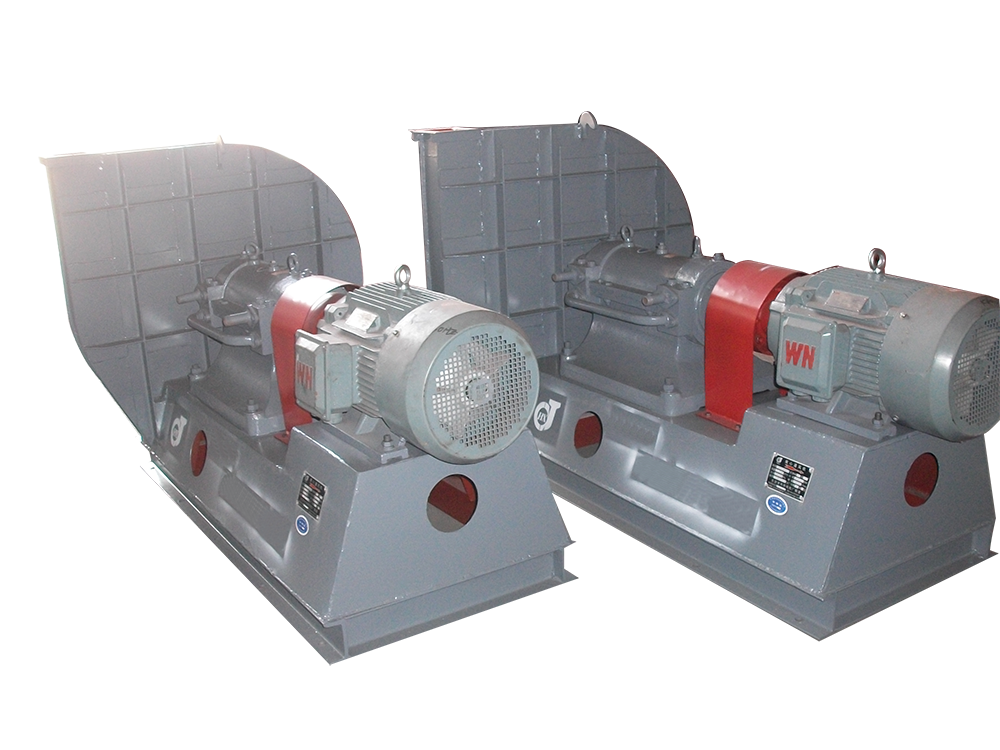
(3) The main faults and causes of the fan may occur during the operation of the fan. For the faults generated, the causes must be quickly identified and solved in time to prevent accidents. Faults in the Operation of 4-72-12 Centrifugal Fan and the Causes Table Fault Name Causes Severe Vibration of Bearing Box 1. The fan shaft is different from the motor shaft, and the coupling is installed askew. 2. The casing or air inlet rubs with the impeller. 3. The foundation stiffness is not enough or firm. 4. Impeller rivet is loose or wheel disc is deformed. 5. The impeller shaft disk and shaft are loose, and the coupling bolt is movable. 6. The connection between casing and bracket, bearing box and bracket, bearing box and seat is loose. 7. The air inlet and outlet pipes of the fan are poorly installed, causing vibration. 8. The rotor is unbalanced. Bearing temperature rise is too high 1. The bearing box vibrates violently. 2. The lubricating grease is poor in quality, deteriorated or overfilled, or contains dust, sand, dirt and other impurities. 3. The tightening force of connecting bolts of bearing cover seat is too large or too small. 4. The shaft and rolling bearing are installed askew, and the front and rear bearings are not concentric. 5. The rolling bearing is damaged. The motor current is too high and the temperature rise is too high. 1. The throttle valve in the air inlet pipe is not closed tightly when driving. 2. The flow exceeds the specified value, or the air duct leaks. 3. The gas density conveyed by the fan is too high. 4. The input voltage of the motor is too low or the power supply is cut off individually. 5. The coupling is improperly connected, the leather ring is too tight or the gap is uneven. 6. Affected by the violent vibration of the bearing box. 7. Affected by deterioration or failure of parallel fans. When the belt slides down, the two pulleys are not in the same plane with each other. Belt runout The distance between two pulleys is too close or the belt is too long.

major Dust exhaust centrifugal fan The reasons for failure caused by unstable operation are: improper temperature control of insulator box; The gas distributor grid is blocked, and the sediment electrode has too thick scale; Improper adjustment of water film; The oxygen content in the system exceeds the standard. ① Insufficient steam pressure and blocked steam pipeline may cause low temperature of insulator box. In the long run, the insulator surface temperature is low, and tar and dust particles accumulate, causing electric field short circuit. If the temperature of insulator box rises too fast, or the temperature changes violently during operation, the insulator will be cracked. ② Dust exhaust centrifugal fan manufactor If intermittent flushing cannot be carried out as required during operation, the tar accumulated on the sediment pipe wall is difficult to be thoroughly cleaned, which, accumulated over time, not only causes excessive resistance to equipment operation, but also leads to damage to the electric field. ③ During maintenance, the water film is not adjusted as required, the water film is uneven or not thick enough, and after putting into operation, the phenomenon described in fault (4) will occur. The above situation also occurs when the water film is damaged during operation. ④ The reason for the explosion of the electrostatic precipitator is that the oxygen content in the gas exceeds the standard, the mixed explosive gas is formed in the equipment and reaches the explosion limit, and the explosion occurs when encountering electric sparks.

Dust leakage may occur when the wet electrostatic precipitator is used at ordinary times, so that the precipitator can not achieve the expected use effect when it is used Dust exhaust centrifugal fan manufactor Let's specifically analyze the causes of dust leakage. 1. The dust remover is mainly assembled from the clean air chamber and the hopper. In this part, screws are used at the connection position between the upper box and the hopper. If the sealing strip used in this place is unqualified, dust will leak out. In addition to affecting the normal use of the equipment, the poor performance of the dust remover in use will have a great impact on the environment of the whole workshop and the surrounding environment. Even some wet electrostatic precipitators have a lot of materials with recycling value in the recycled dust. two Dazhou major Dust exhaust centrifugal fan Improper filtering wind speed used in dedusting may also lead to dust leakage, because the dust will be adsorbed on the filter bag when the temperature is too high, so the resistance of dedusting equipment will increase when it is used, leading to leakage. 3. The dedusting bag is also a device that plays a major role in the operation and use of the equipment. If the density of the bag itself is relatively small, it may cause dust leakage to each other. Therefore, when selecting the bag, it is also necessary to select the one with better quality for use, and it is also necessary to do a good job of maintenance when using it again.
Selection and application of fan performance (I) Description of fan performance: 1. № 10, 12, 16, 20 are converted according to dimensionless performance of № 10 model. 2. № 5, 6, 8 are converted according to dimensionless performance of № 5 model. 3. № 5 and below shall be determined according to the performance of the measured prototype. Note: According to the dimensionless performance curve conversion formula, total pressure H=ρ u2 H (Pa) flow Q=900 π D22 uQ (m3/h) shaft power N=N × D22u3 ρ/4000 (kw), where D2 - impeller outer diameter (m) u - impeller outer edge linear speed (m/s) ρ - gas density (Kg/m3), the required power rate shall be based on shaft power plus mechanical loss and motor reserve. 4. The solid line is № 5 model, and the dotted line is № 10 model. The performance of the fan is expressed by the flow, total pressure, main shaft speed, shaft power, efficiency and other parameters of the fan, and there are certain relationships between the parameters, which are listed in the following table. The relationship of fan performance parameters changes density ρ, speed n changes speed n, atmospheric pressure P, gas temperature t Q1/Q2=n1/n2 H1/H2=(n1/n2) 2 ρ 1/ρ 2 N1/N2=(n1/n2) 3 ρ 1/ρ 2 η 1=η 2 Q1/Q2=n1/n2 H1/H2=(n1/n2) 2 (P1/P2) (273+t2/273+t1) N1/N2=(n1/n2) 3 (P1/P2) (273+t2/273+t1) η 1=η 2 Note: 1. In the middle, Q represents flow (m3/h), H represents total pressure (Pa), N represents shaft power (kw), η represents full pressure efficiency, ρ represents density (kg/m3), t represents temperature (℃), n represents speed (r/min), and P represents atmospheric pressure (Pa). 2. The footnote symbol 2 indicates the known performance and related parameters, and the footnote symbol 1 indicates the required performance and related parameters. (


