The wet electrostatic precipitator is a new kind of dust removal equipment used to treat micro dust and micro particles, customized Boiler centrifugal fan It is mainly used to remove dust, acid mist, water droplets, aerosols, odor, PM2.5 and other harmful substances in humid gases, and is an ideal equipment for controlling atmospheric dust pollution. The wet electrostatic precipitator is usually referred to as WESP, which has the same basic principle as the dry electrostatic precipitator. It goes through three stages: charging, collection and dust removal. The principle of wet electrostatic precipitator is the same as that of dry electrostatic precipitator, Shangrao Boiler centrifugal fan The dust is charged by high-voltage corona discharge, and the charged dust reaches the dust collecting plate/tube under the action of electric field force. The dry electrostatic precipitator mainly deals with dry gas with very low water content, while the wet electrostatic precipitator mainly deals with wet gas with high water content or even saturation. There is a big difference between WESP and DESP in the way of removing the dust collected on the dust collecting plate/pipe. The dry electrostatic precipitator generally uses mechanical rapping or acoustic cleaning to remove the dust on the electrode, while the wet electrostatic precipitator uses regular flushing to remove the dust along with the flow of flushing fluid
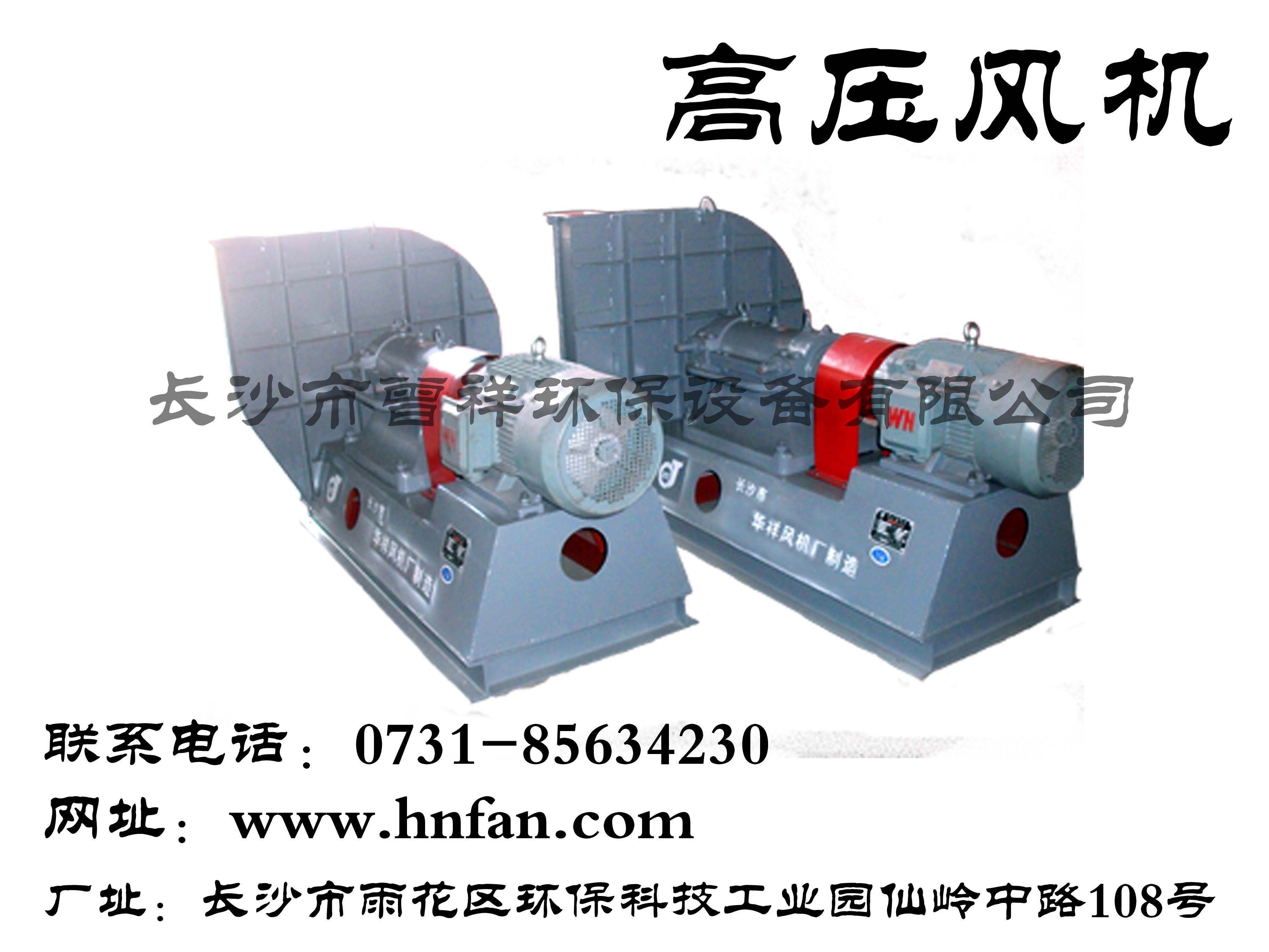
Shangrao customized Boiler centrifugal fan Fan performance parameters. The performance parameters of fan mainly include flow, pressure, power, efficiency and speed. In addition, the size of noise and vibration is also the main fan design index. Flow, also known as air volume, is expressed by the volume of gas flowing through the fan in unit time; Pressure, also known as wind pressure, refers to the pressure rise value of gas in the fan, including static pressure, dynamic pressure and total pressure; Power refers to the input power of the fan, namely shaft power. The ratio of effective power of fan to shaft power is called efficiency. Boiler centrifugal fan manufactor The total pressure efficiency of fan can reach 90%. Fans are widely used for ventilation, dust discharge and cooling of factories, mines, tunnels, cooling towers, vehicles, ships and buildings; Ventilation and induced draft of boiler and industrial furnace; Cooling and ventilation in air conditioning equipment and household appliances; Drying and selection of grain; Wind source of wind tunnel and inflation and propulsion of hovercraft. The working principle of the fan is basically the same as that of the turbine compressor, but because the gas flow rate is low and the pressure changes little, it is generally unnecessary to consider the change of gas specific volume, that is, treat the gas as an incompressible fluid
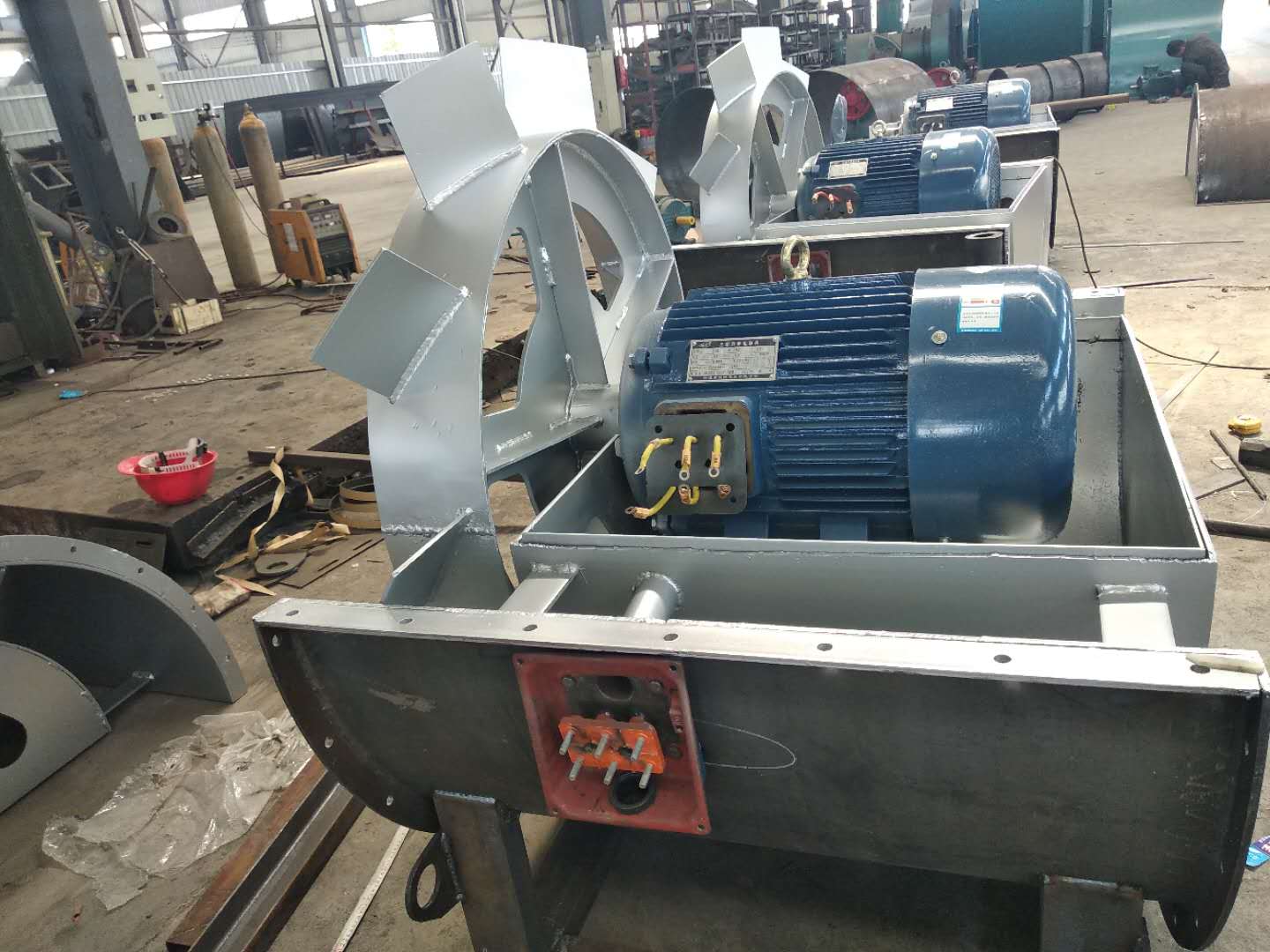
Gas compression and gas transmission machinery is a machine that converts rotating mechanical energy into gas pressure energy and kinetic energy and transports gas. The main structural components of the fan are impeller, casing, air inlet, support, motor, pulley, coupling, silencer, transmission parts (bearings), etc. customized Boiler centrifugal fan The unpowered fan uses the air thermal convection caused by the natural wind force and the indoor and outdoor temperature difference to drive the turbine to rotate, thus using the centrifugal force and negative pressure effect to exhaust the indoor stale hot air. Shangrao Boiler centrifugal fan manufactor The fan is related to the transmission and distribution energy consumption of the system, and is a very critical part of building energy conservation. According to the fan inspection conducted by the National Air Conditioning Equipment Quality Supervision and Inspection Center for many years, many fans have problems under rated conditions, so it is necessary to produce and manufacture fans in strict accordance with product standards. customized Boiler centrifugal fan At the beginning of the fan operation, the vibration of the bearing is very small, but with the extension of the operating time, the dust in the fan will be unevenly attached to the impeller, gradually destroying the dynamic balance of the fan, making the bearing vibration gradually increase. Once the vibration reaches the maximum allowable value of 11mm/s of the fan (the maximum allowable value expressed by the amplitude value is as follows), The fan must be shut down for repair (dust accumulation shall be removed and dynamic balance shall be redone). Because it is very dangerous at this time, users must not use it forcibly. When the fan vibration is close to the dangerous value, the vibration measuring instrument will give an alarm.
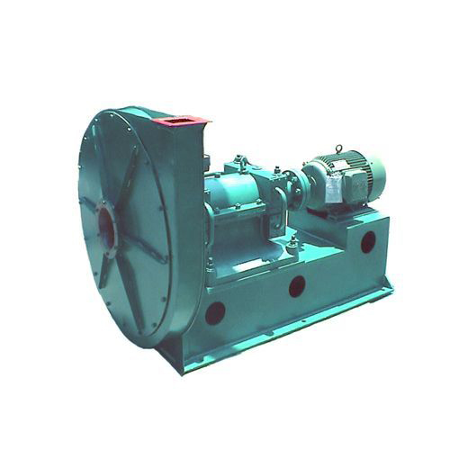
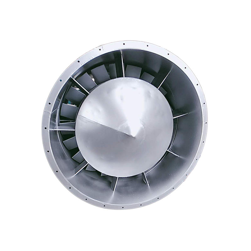
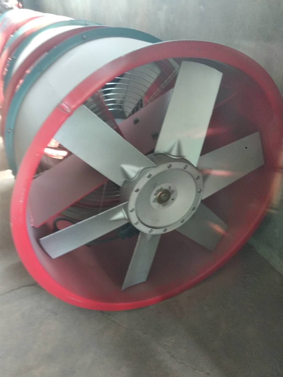
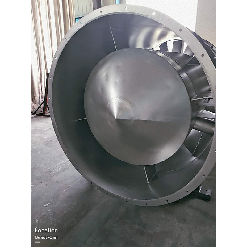
Fans can be classified into several types according to the materials used, such as iron shell fans (ordinary fans), glass fiber reinforced plastic fans, plastic fans, aluminum fans, stainless steel fans, etc. Boiler centrifugal fan manufactor In the direction of gas flow. Fans can be classified into centrifugal, axial, diagonal (mixed flow) and cross flow fans according to the direction of gas flow. (1) Centrifugal fan. The airflow enters the impeller of the fan axially and flows mainly along the radial direction. This type of fan is made according to the principle of centrifugal action, and its products include centrifugal fan, centrifugal blower and centrifugal compressor. (2) Axial flow fan. The airflow enters the impeller of the fan axially and flows approximately along the axis on the cylindrical surface. Such fans include axial fans, axial blowers and axial compressors. (3) Rotary fan. Shangrao customized Boiler centrifugal fan Use the rotor rotation to change the air chamber volume to work. Common varieties include Roots blower and rotary compressor.
(3) The main faults and causes of the fan may occur during the operation of the fan. For the faults generated, the causes must be quickly identified and solved in time to prevent accidents. Faults in the Operation of 4-72-12 Centrifugal Fan and the Causes Table Fault Name Causes Severe Vibration of Bearing Box 1. The fan shaft is different from the motor shaft, and the coupling is installed askew. 2. The casing or air inlet rubs with the impeller. 3. The foundation stiffness is not enough or firm. 4. Impeller rivet is loose or wheel disc is deformed. 5. The impeller shaft disk and shaft are loose, and the coupling bolt is movable. 6. The connection between casing and bracket, bearing box and bracket, bearing box and seat is loose. 7. The air inlet and outlet pipes of the fan are poorly installed, causing vibration. 8. The rotor is unbalanced. Bearing temperature rise is too high 1. The bearing box vibrates violently. 2. The lubricating grease is poor in quality, deteriorated or overfilled, or contains dust, sand, dirt and other impurities. 3. The tightening force of connecting bolts of bearing cover seat is too large or too small. 4. The shaft and rolling bearing are installed askew, and the front and rear bearings are not concentric. 5. The rolling bearing is damaged. The motor current is too high and the temperature rise is too high. 1. The throttle valve in the air inlet pipe is not closed tightly when driving. 2. The flow exceeds the specified value, or the air duct leaks. 3. The gas density conveyed by the fan is too high. 4. The input voltage of the motor is too low or the power supply is cut off individually. 5. The coupling is improperly connected, the leather ring is too tight or the gap is uneven. 6. Affected by the violent vibration of the bearing box. 7. Affected by deterioration or failure of parallel fans. When the belt slides down, the two pulleys are not in the same plane with each other. Belt runout The distance between two pulleys is too close or the belt is too long.
2. The influence of the total pressure deviation Δ H of the fan itself was not considered during selection. When the actual total pressure of the fan was positive deviation, the flow increased; When the actual total pressure of the fan is negative deviation, the flow decreases. See (a) below. The relationship between the deviation of the pipe network characteristic curve and the total pressure and the flow can be eliminated by one of the following methods when the fan starts to officially operate after new installation, or when the flow is too large or too small during use. 1. Use the opening and closing of throttling device to adjust the flow. 2. Increase or decrease the flow by increasing or decreasing the fan speed. 3. Use a new fan with higher or lower pressure to increase or decrease the flow. 4. Change the pipe network to reduce the resistance coefficient of the pipe network to increase the flow. It must be pointed out that throttling devices are generally used to regulate the flow. However, when the actual flow is much larger than the required flow, this method wastes too much power and is very uneconomical. If conditions permit, the fan speed is usually reduced or the fan with lower pressure is replaced. When the throttling device is fully open, the flow is still too small. At this time, the throttling device has lost its function, so try to reduce the resistance coefficient of the pipe network to increase the flow, or increase the fan speed and replace the fan with higher pressure. However, the speed of the fans directly connected to the motor and the coupling cannot be changed generally. Only the fan driven by the pulley can increase or decrease the speed by changing the diameter of the pulley, but the speed of the fan cannot exceed the speed max in the performance and selection table.


