(3) The main faults and causes of the fan may occur during the operation of the fan. For the faults generated, the causes must be quickly identified and solved in time to prevent accidents. Faults in the Operation of 4-72-12 Centrifugal Fan and the Causes Table Fault Name Causes Severe Vibration of Bearing Box 1. The fan shaft is different from the motor shaft, and the coupling is installed askew. 2. The casing or air inlet rubs with the impeller. 3. The foundation stiffness is not enough or firm. 4. Impeller rivet is loose or wheel disc is deformed. 5. The impeller shaft disk and shaft are loose, and the coupling bolt is movable. 6. The connection between casing and bracket, bearing box and bracket, bearing box and seat is loose. 7. The air inlet and outlet pipes of the fan are poorly installed, causing vibration. 8. The rotor is unbalanced. Bearing temperature rise is too high 1. The bearing box vibrates violently. 2. The lubricating grease is poor in quality, deteriorated or overfilled, or contains dust, sand, dirt and other impurities. 3. The tightening force of connecting bolts of bearing cover seat is too large or too small. 4. The shaft and rolling bearing are installed askew, and the front and rear bearings are not concentric. 5. The rolling bearing is damaged. The motor current is too high and the temperature rise is too high. 1. The throttle valve in the air inlet pipe is not closed tightly when driving. 2. The flow exceeds the specified value, or the air duct leaks. 3. The gas density conveyed by the fan is too high. 4. The input voltage of the motor is too low or the power supply is cut off individually. 5. The coupling is improperly connected, the leather ring is too tight or the gap is uneven. 6. Affected by the violent vibration of the bearing box. 7. Affected by deterioration or failure of parallel fans. When the belt slides down, the two pulleys are not in the same plane with each other. Belt runout The distance between two pulleys is too close or the belt is too long.
Correct maintenance is an important guarantee for the safe and reliable operation of the fan and the improvement of its service life. Therefore, Dust removal equipment Price When using fans, full attention must be paid. Impeller maintenance: at the initial stage of impeller operation and during all regular inspections, whenever there is an opportunity, the impeller must be checked for cracks, wear, dust and other defects. The impeller must be kept clean whenever possible, customized Dust removal equipment The steel wire brush shall be used regularly to remove the dust and rust on the impeller. As the travel time increases, the dust can not be evenly attached to the impeller, which will cause damage to the balance of the impeller and even cause rotor vibration. As long as the impeller is repaired, it needs to be dynamically balanced again. If possible, the portable trial dynamic balancing instrument can be used for on-site balancing. Before dynamic balancing, check whether all fastening bolts are tightened. Since the impeller has been operating in an unbalanced state for a period of time, these bolts may have become loose. Bearing maintenance: frequently check the oil supply of bearing lubricating oil. If the box leaks oil, tighten the bolts of the end cover a little. If this is not enough, you may have to use new sealing packing. When the bearing lubricating oil is in normal use, it should be replaced at least once every six months. When it is used for the first time, it should be done after 200 hours of operation. The second oil change should be done in 1 to 2 months. After that, the lubricating oil should be checked once a week. If the lubricating oil does not deteriorate, the oil change can be extended to 2 to 4 months. The specified brand of lubricating oil (specified on the general drawing) must be used when replacing, The old oil in the oil tank shall be completely drained and cleaned before new oil can be filled. If the fan bearing needs to be replaced, pay attention to the following matters: before installing the new bearing, the bearing and bearing box must be very clean. Place the bearing in the oil with a temperature of about 70~80 ℃ and heat it before installing it on the shaft. Do not force assembly to avoid damaging the shaft. Maintenance of other supporting equipment: see the respective user manual for the maintenance of various supporting equipment, including motors, electric actuators, instruments, meters, etc. These operating instructions are provided by each supporting manufacturer. The manufacturer will pack these instructions together and provide them to the user
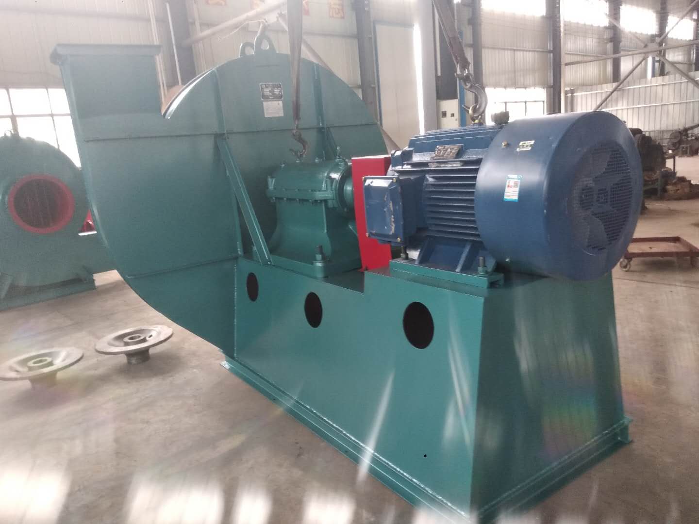
customized Dust removal equipment Common fault: the working medium of the fan in the cement industry often contains a certain amount of homogeneous particles with different sizes and shapes, such as the induced draft fan of the dust removal system and the blower for pneumatic conveying. Because these fans work in the dusty air flow, the dust particles in the air flow will not only wear the fan, but also attach ash on the fan blades, and the wear and ash deposition are uneven. As a result, the balance of the fan rotor is destroyed, which causes the fan vibration and shortens the life of the fan. In serious cases, the fan can not work normally. In particular, the fan blades are most severely worn, Dust removal equipment Price It not only destroys the flow characteristics in the fan, but also easily leads to major accidents such as blade fracture and runaway. The wear of transmission parts is also a common problem of fans, including various shafts, rollers, reducers, motors, pumps and other bearing positions, bearing seats, keyways, threads and other parts. The traditional repair welding machine processing method is easy to cause material damage, resulting in deformation or fracture of parts, with greater limitations; Brush plating and spray re machining methods often require outsourcing, which not only requires long repair cycle and high cost, but also can not fundamentally solve the causes of wear (poor impact resistance and yield of metal) because the repair materials are metal materials; Many parts can only be scrapped and replaced, which greatly increases the production cost and inventory of spare parts, leaving the enterprise's good resource advantage idle and wasted
Dust removal equipment Price The work starts before the fan is used. one Guangdong Dust removal equipment Price Carefully read the fan operation instructions and product samples, and be familiar with and understand the fan specifications, forms, impeller rotation direction and air flow in and out direction; Check whether all parts of the fan are in good condition again, or they can be installed and used only after being repaired. 2. The fan must be installed with safety devices to prevent accidents, and installed and wired by professionals familiar with relevant safety requirements. 3. The air duct connecting the inlet and outlet of the fan has separate support, and it is not allowed to add the overlapping weight of the duct to the components of the fan; When installing the fan, pay attention to the horizontal position of the fan, and adjust the connection between the joint surface of the fan and the foundation and the air outlet pipe to make it coincide naturally. Forced connection is not allowed. four customized Dust removal equipment After the fan is installed, move the impeller by hand or lever to check whether it is too tight or rubbed, and whether there is any object that hinders the rotation. The test run can be carried out only when there is no abnormal phenomenon. The exposed part of the fan transmission device should be equipped with a protective cover (provided by the user). If the fan inlet is not connected, a protective screen or other installation device (provided by the user) should also be added. 5. The power distribution control box of the fan must match the corresponding fan (power, voltage, pneumatic mode, control mode, etc.). 6. The fan wiring should be made by a professional electrician, and the wiring must be correct and reliable. Especially, the wiring number at the electric control box should be consistent with the number on the fan terminal. The fan shell should be reliably grounded. The grounding must be reliable, and zero connection cannot be used instead of grounding. 7. After all fans are installed, check whether there are any left tool box sundries inside the fan
Emergency stop: customized Dust removal equipment Price In case of one of the following situations during the unit commissioning, emergency shutdown shall be carried out immediately. The emergency stop operation is to press the stop button of the main motor, and then carry out the remedial work after the shutdown; The centrifugal fan suddenly vibrates strongly and has exceeded the trip value; There is scratch or abnormal friction sound inside the machine body; customized Dust removal equipment Smoke occurs at any bearing or seal, or the temperature of a bearing rises sharply to the alarm value; When the oil pressure is lower than the alarm value and cannot be restored to normal; The liquid level in the oil tank is low, and there is suction phenomenon; When the axial displacement value increases significantly and reaches the alarm value;
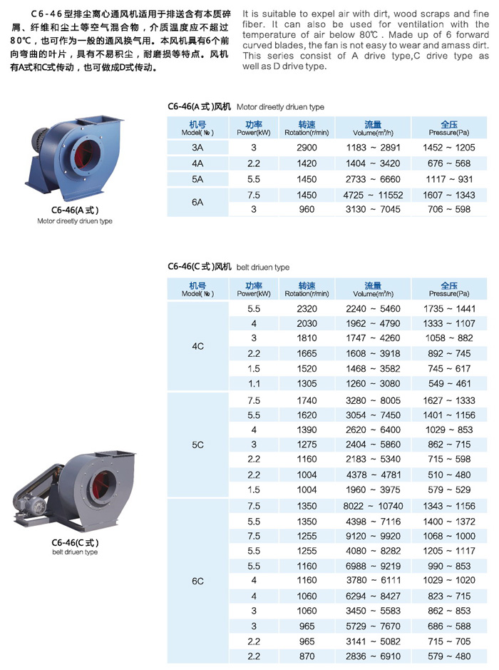
Selection and application of fan performance (I) Description of fan performance: 1. № 10, 12, 16, 20 are converted according to dimensionless performance of № 10 model. 2. № 5, 6, 8 are converted according to dimensionless performance of № 5 model. 3. № 5 and below shall be determined according to the performance of the measured prototype. Note: According to the dimensionless performance curve conversion formula, total pressure H=ρ u2 H (Pa) flow Q=900 π D22 uQ (m3/h) shaft power N=N × D22u3 ρ/4000 (kw), where D2 - impeller outer diameter (m) u - impeller outer edge linear speed (m/s) ρ - gas density (Kg/m3), the required power rate shall be based on shaft power plus mechanical loss and motor reserve. 4. The solid line is № 5 model, and the dotted line is № 10 model. The performance of the fan is expressed by the flow, total pressure, main shaft speed, shaft power, efficiency and other parameters of the fan, and there are certain relationships between the parameters, which are listed in the following table. The relationship of fan performance parameters changes density ρ, speed n changes speed n, atmospheric pressure P, gas temperature t Q1/Q2=n1/n2 H1/H2=(n1/n2) 2 ρ 1/ρ 2 N1/N2=(n1/n2) 3 ρ 1/ρ 2 η 1=η 2 Q1/Q2=n1/n2 H1/H2=(n1/n2) 2 (P1/P2) (273+t2/273+t1) N1/N2=(n1/n2) 3 (P1/P2) (273+t2/273+t1) η 1=η 2 Note: 1. In the middle, Q represents flow (m3/h), H represents total pressure (Pa), N represents shaft power (kw), η represents full pressure efficiency, ρ represents density (kg/m3), t represents temperature (℃), n represents speed (r/min), and P represents atmospheric pressure (Pa). 2. The footnote symbol 2 indicates the known performance and related parameters, and the footnote symbol 1 indicates the required performance and related parameters. (


