(3) The main faults and causes of the fan may occur during the operation of the fan. For the faults generated, the causes must be quickly identified and solved in time to prevent accidents. Faults in the Operation of 4-72-12 Centrifugal Fan and the Causes Table Fault Name Causes Severe Vibration of Bearing Box 1. The fan shaft is different from the motor shaft, and the coupling is installed askew. 2. The casing or air inlet rubs with the impeller. 3. The foundation stiffness is not enough or firm. 4. Impeller rivet is loose or wheel disc is deformed. 5. The impeller shaft disk and shaft are loose, and the coupling bolt is movable. 6. The connection between casing and bracket, bearing box and bracket, bearing box and seat is loose. 7. The air inlet and outlet pipes of the fan are poorly installed, causing vibration. 8. The rotor is unbalanced. Bearing temperature rise is too high 1. The bearing box vibrates violently. 2. The lubricating grease is poor in quality, deteriorated or overfilled, or contains dust, sand, dirt and other impurities. 3. The tightening force of connecting bolts of bearing cover seat is too large or too small. 4. The shaft and rolling bearing are installed askew, and the front and rear bearings are not concentric. 5. The rolling bearing is damaged. The motor current is too high and the temperature rise is too high. 1. The throttle valve in the air inlet pipe is not closed tightly when driving. 2. The flow exceeds the specified value, or the air duct leaks. 3. The gas density conveyed by the fan is too high. 4. The input voltage of the motor is too low or the power supply is cut off individually. 5. The coupling is improperly connected, the leather ring is too tight or the gap is uneven. 6. Affected by the violent vibration of the bearing box. 7. Affected by deterioration or failure of parallel fans. When the belt slides down, the two pulleys are not in the same plane with each other. Belt runout The distance between two pulleys is too close or the belt is too long.
Main factors affecting the dust removal efficiency of wet electrostatic precipitator. The effect of electrostatic voltage, water volume and dust concentration on wet electrostatic precipitation efficiency is positive, that is, the dust removal efficiency increases with the increase of voltage, water volume and dust concentration. Among them, voltage has the most significant effect on dust removal efficiency, followed by water volume, and dust concentration has the least effect. The combination of static electricity and water mist can significantly improve the dust removal efficiency. The role of water in wet electrostatic precipitation. The water in wet electrostatic precipitator mainly exists as atomized water droplets. According to domestic research, water mist has a series of effects on the improvement of dust removal efficiency of wet electrostatic precipitator, major Wet electrostatic precipitator Main mechanism: the water mist can keep the discharge electrode clean and keep the corona vigorous; The mist particles strike the dust collecting electrode to form a thin and uniform water film, Anshun Wet electrostatic precipitator It can prevent the "secondary flying" of low specific resistance dust from tempering high specific resistance dust and prevent the occurrence of "reverse corona"; For the dust with strong viscosity, the electrode can be prevented from sticking; It is also suitable for collecting those flammable and explosive dust. The water mist is sprayed directly to the discharge electrode and corona area, and the discharge electrode also acts as an atomizer. The same power supply can realize corona discharge, water atomization, water mist and dust particle charging, realizing the organic combination of static electricity and water mist. The water mist is directly sprayed to the discharge electrode, which has a high charge. The collision interception, adsorption and coagulation of water mist with high charge mass ratio in the electric field can greatly improve the dust removal efficiency. The water mist strikes the dust collecting electrode to form water flow down, so that the dust collecting electrode is always kept clean, eliminating the vibrating device, and avoiding a series of problems caused by vibrating dust removal in dry dust removal. In the method of spraying water mist to the discharge electrode and corona area to further atomize the water mist, the static electricity does not directly contact the spray device, so there is almost no insulation problem. This method is completely different from the dedusting technology of "corona discharge atomizes water". The latter is almost impossible to insulate due to the direct contact between water and electricity, and it is actually difficult to achieve industrial application. The barbed electrode can produce a strong electrostatic field, and has a good corona discharge capacity. The electrostatic and water mist work together, and has a high dust removal efficiency
The wet electrostatic precipitator is mainly used to purify water vapor, odor, acid mist and other harmful substances in the exhaust gas discharged by the factory. As an air pollution control equipment, it has also been widely used. let's Wet electrostatic precipitator company Understand its system composition together. 1. Composition of wet electrostatic precipitator system. According to its working principle, the control system of wet electrostatic precipitator generally includes high pressure system, water treatment system, low pressure heating and hot air purging system, upper computer system, etc. 2. Design of wet electrostatic precipitator system. (1) major Wet electrostatic precipitator High voltage system and wet electrostatic precipitator charge the dust through corona discharge of high voltage system. The charged dust reaches the dust collecting plate under the effect of electric field force, and then the dust is removed by regular scouring. (2) Anshun major Wet electrostatic precipitator Water treatment system. This system deals with the problem of secondary water pollution. It is mainly the water discharged after equipment spraying and flushing, which contains a lot of acid substances and fine particles. Direct discharge will cause secondary pollution. The recycling of water in the equipment consists of two steps: neutralization and acid removal, and separation of suspended solids, so that the sewage can be turned into industrial water suitable for spraying. (3) Heating system. The heating system includes insulator incubator heating, hot air purging heating, and the hot air purging system is composed of fan, butterfly valve and heater. When it starts actively, it starts in the order of fan, butterfly valve and heater. When actively closing, it shall be closed in reverse order. (4) Upper computer system. The selected upper computer system is an industrial control computer, and the network front-end computer is used to enable the system to have extraordinary data acquisition and processing capabilities, so as to meet the requirements of wet electrostatic precipitator for centralized management, decentralized control, energy conservation and emission reduction.
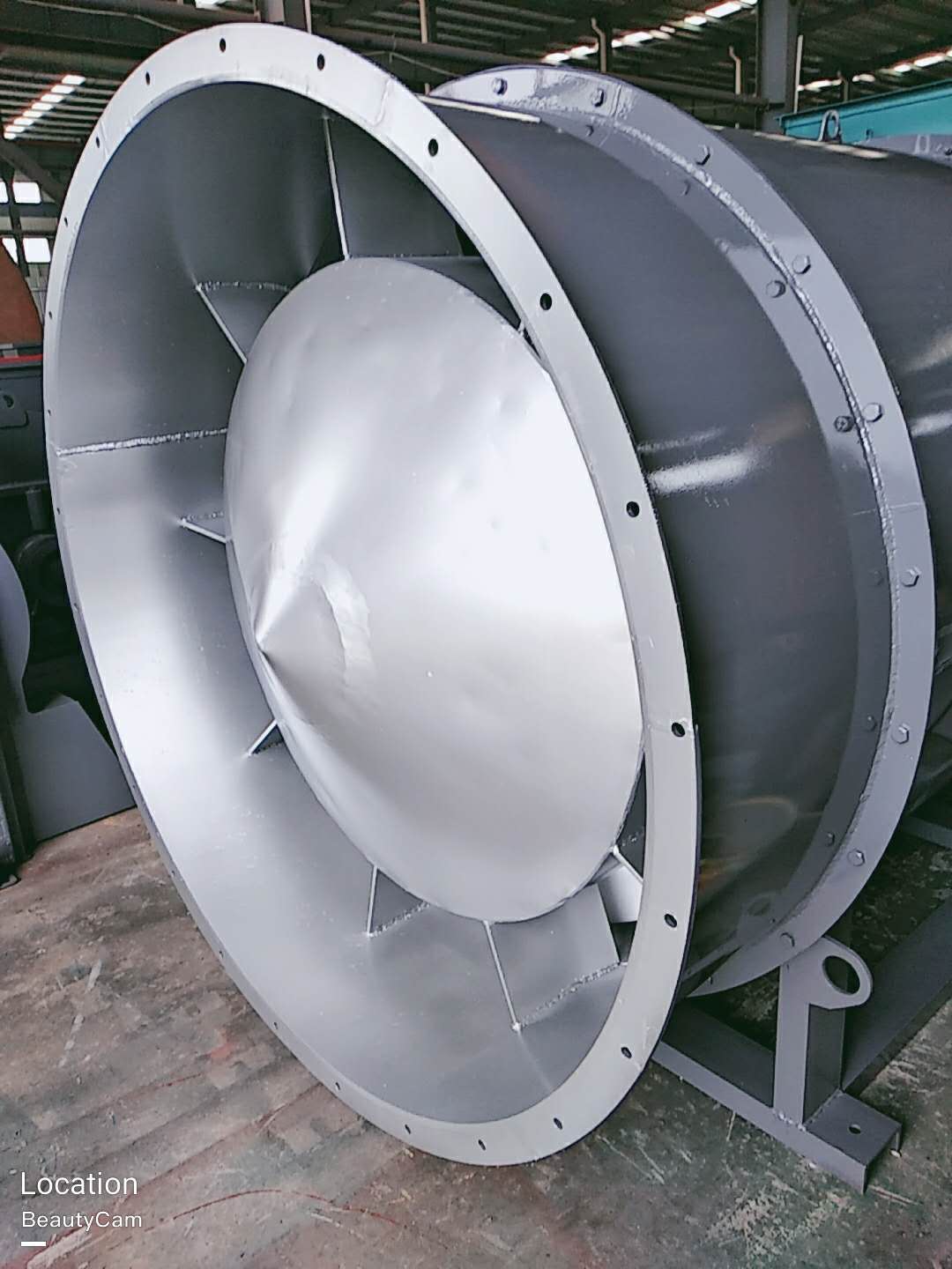
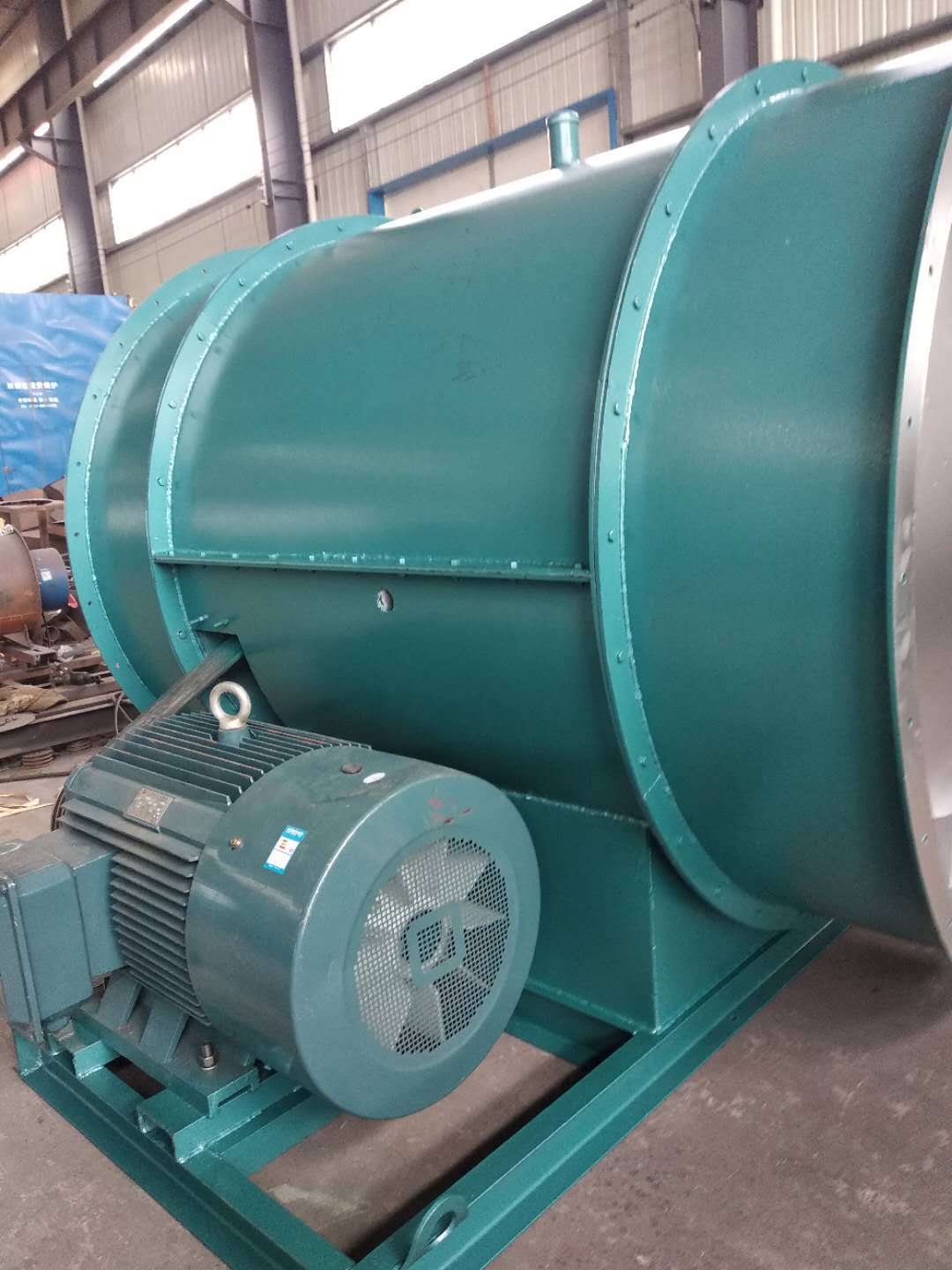
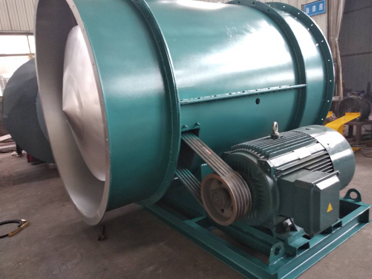
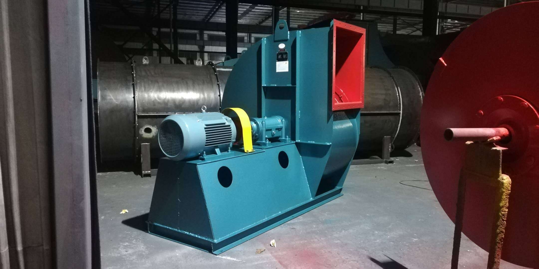
Before installation, first prepare the materials and tools for installation, and check the parts of the fan, especially the impeller, main shaft, bearing and other parts. If any damage is found, repair it, and then clean the inside of the bearing box with kerosene. In the process of installation, the following points must be paid attention to: 1. In order to prevent rust and reduce the difficulty of disassembly, some grease or machine oil should be coated on some joint surfaces. 2. When installing the bolts on the joint surface, if there are positioning pins, install the pins and tighten them before tightening the bolts. 3. Check that there should be no tools and sundries falling or left in the casing and other casings. Installed and used by CHANG factory bridge QIAO ISO9001 quality management system certification enterprise of Beijing No. 2 Blower Works 1. When installing the fan, the inlet and outlet must be provided with soft connection, and the weight of the gas transmission pipeline should not be added to the casing. Correct the gap size between the air inlet and the impeller according to the drawing, and keep the shaft in a horizontal position. 2. When installing the soft connection of the air inlet, the bolts of the air inlet itself can be directly used for connection. At this time, the air inlet is fixed by three countersunk screws.
Emergency stop: major Wet electrostatic precipitator company In case of one of the following situations during the unit commissioning, emergency shutdown shall be carried out immediately. The emergency stop operation is to press the stop button of the main motor, and then carry out the remedial work after the shutdown; The centrifugal fan suddenly vibrates strongly and has exceeded the trip value; There is scratch or abnormal friction sound inside the machine body; major Wet electrostatic precipitator Smoke occurs at any bearing or seal, or the temperature of a bearing rises sharply to the alarm value; When the oil pressure is lower than the alarm value and cannot be restored to normal; The liquid level in the oil tank is low, and there is suction phenomenon; When the axial displacement value increases significantly and reaches the alarm value;
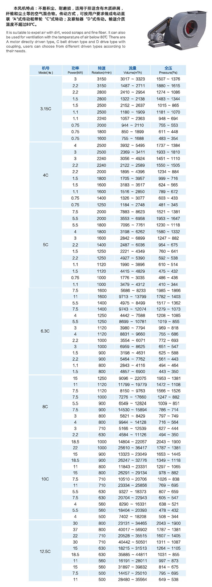
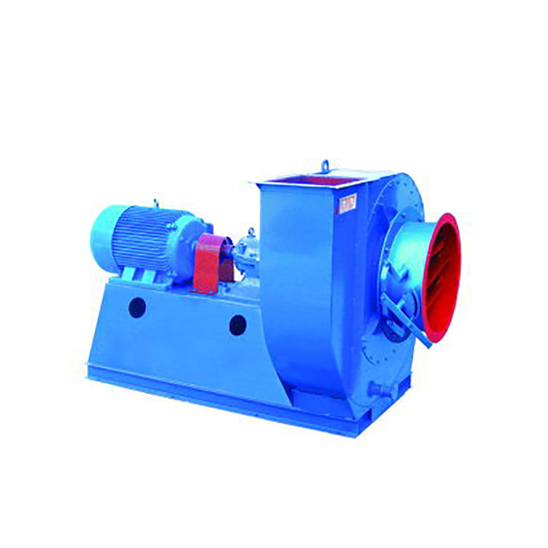
Selection and application of fan performance (I) Description of fan performance: 1. № 10, 12, 16, 20 are converted according to dimensionless performance of № 10 model. 2. № 5, 6, 8 are converted according to dimensionless performance of № 5 model. 3. № 5 and below shall be determined according to the performance of the measured prototype. Note: According to the dimensionless performance curve conversion formula, total pressure H=ρ u2 H (Pa) flow Q=900 π D22 uQ (m3/h) shaft power N=N × D22u3 ρ/4000 (kw), where D2 - impeller outer diameter (m) u - impeller outer edge linear speed (m/s) ρ - gas density (Kg/m3), the required power rate shall be based on shaft power plus mechanical loss and motor reserve. 4. The solid line is № 5 model, and the dotted line is № 10 model. The performance of the fan is expressed by the flow, total pressure, main shaft speed, shaft power, efficiency and other parameters of the fan, and there are certain relationships between the parameters, which are listed in the following table. The relationship of fan performance parameters changes density ρ, speed n changes speed n, atmospheric pressure P, gas temperature t Q1/Q2=n1/n2 H1/H2=(n1/n2) 2 ρ 1/ρ 2 N1/N2=(n1/n2) 3 ρ 1/ρ 2 η 1=η 2 Q1/Q2=n1/n2 H1/H2=(n1/n2) 2 (P1/P2) (273+t2/273+t1) N1/N2=(n1/n2) 3 (P1/P2) (273+t2/273+t1) η 1=η 2 Note: 1. In the middle, Q represents flow (m3/h), H represents total pressure (Pa), N represents shaft power (kw), η represents full pressure efficiency, ρ represents density (kg/m3), t represents temperature (℃), n represents speed (r/min), and P represents atmospheric pressure (Pa). 2. The footnote symbol 2 indicates the known performance and related parameters, and the footnote symbol 1 indicates the required performance and related parameters. (


