The selection of fans Product performance and fan performance listed in the selection table are based on the performance of delivering air under standard conditions. Therefore, when the use condition is non-standard, the H4-72-12 centrifugal fan must convert the use performance into the performance under standard conditions according to the relationship in the table above, and then select according to the performance and selection table. (3) Treatment of excessive or insufficient flow During use, excessive or insufficient flow often occurs. There are many reasons for this phenomenon. If the flow is high and low during use, it is mainly because the resistance in the pipe network is high and low, or the fan works in a non working area. If it is gradually reduced after a long time during use, it is mainly due to pipe network blockage. After the fan is newly installed, the flow is too large or insufficient during the formal operation. The main reasons for this phenomenon are as follows: 1. The actual value of pipe network resistance is too different from the calculated value. In the general pipe network characteristic equation, H=KQ2, if the actual value K of K-resistance coefficient is less than the calculated value K, the flow will increase; If the actual value K is greater than the calculated value K, the flow decreases. See (b) below.
3. When installing Type C and Type B, ensure that the two pulley positions are on the same plane, and the flatness tolerance is 0.5mm. 4. When installing Type D, use a dial indicator and feeler gauge to measure the coaxiality of the fan spindle and motor spindle and the parallelism of both ends of the coupling. The coaxiality tolerance of two shafts is 0.2mm, the parallelism tolerance of both ends of the coupling is 0.2mm, and the spacing between two planes of the coupling is 5 to 8mm. 5. After the fan is installed, move the rotor with hand or lever to check whether it is too tight or collided. The test run can be carried out without overtightening or collision. 6. After the motor is installed, the belt pulley or coupling guard shall be installed. If the air inlet is not connected to the air inlet pipe, the guard net or other safety devices (provided by the user) shall also be provided. 7. Other parts shall be installed according to the corresponding positions in the drawing. 8. Add N46 (ISO VG46, 30) in summer and N32 (ISO VG32, 20) in winter. The oil level should be at 1/2 of the oil window.

Selection and application of fan performance (I) Description of fan performance: 1. № 10, 12, 16, 20 are converted according to dimensionless performance of № 10 model. 2. № 5, 6, 8 are converted according to dimensionless performance of № 5 model. 3. № 5 and below shall be determined according to the performance of the measured prototype. Note: According to the dimensionless performance curve conversion formula, total pressure H=ρ u2 H (Pa) flow Q=900 π D22 uQ (m3/h) shaft power N=N × D22u3 ρ/4000 (kw), where D2 - impeller outer diameter (m) u - impeller outer edge linear speed (m/s) ρ - gas density (Kg/m3), the required power rate shall be based on shaft power plus mechanical loss and motor reserve. 4. The solid line is № 5 model, and the dotted line is № 10 model. The performance of the fan is expressed by the flow, total pressure, main shaft speed, shaft power, efficiency and other parameters of the fan, and there are certain relationships between the parameters, which are listed in the following table. The relationship of fan performance parameters changes density ρ, speed n changes speed n, atmospheric pressure P, gas temperature t Q1/Q2=n1/n2 H1/H2=(n1/n2) 2 ρ 1/ρ 2 N1/N2=(n1/n2) 3 ρ 1/ρ 2 η 1=η 2 Q1/Q2=n1/n2 H1/H2=(n1/n2) 2 (P1/P2) (273+t2/273+t1) N1/N2=(n1/n2) 3 (P1/P2) (273+t2/273+t1) η 1=η 2 Note: 1. In the middle, Q represents flow (m3/h), H represents total pressure (Pa), N represents shaft power (kw), η represents full pressure efficiency, ρ represents density (kg/m3), t represents temperature (℃), n represents speed (r/min), and P represents atmospheric pressure (Pa). 2. The footnote symbol 2 indicates the known performance and related parameters, and the footnote symbol 1 indicates the required performance and related parameters. (

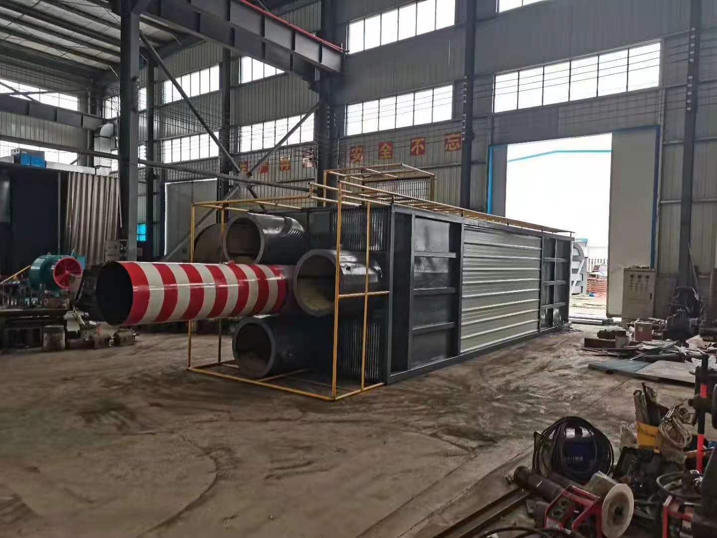
How are dust collectors classified, large Axial flow fan Do you know how to distinguish it and how to define its economic type? Let's talk about it from these aspects. 1. Dust removal efficiency. Mount Huangshan Axial flow fan Dust removal efficiency refers to the ratio of the amount of dust collected by the dust collector to the amount of dust entering the dust collector. According to the total dedusting efficiency, the dedusters can be divided into: low efficiency dedusters (50~80%), medium efficiency dedusters (80~95%) and high efficiency dedusters (more than 95%). 2. Dust removal resistance. The resistance indicates the pressure loss when the airflow passes through the dust remover. According to the resistance, dust collectors can be divided into low resistance dust collectors (Δ P<500Pa), medium resistance dust collectors (Δ P=500 ~ 2000Pa) and high resistance dust collectors (Δ P=2000 ~ 20000Pa). 3. Economy. Economy is one of the important indexes for evaluating dust remover, which includes equipment cost and operation and maintenance cost of dust remover. Among all kinds of dust collectors, the equipment cost of electrostatic precipitator is the highest, followed by bag type dust collector, Venturi tube dust collector, cyclone dust collector is the lowest electrostatic precipitator: the dust removal efficiency is high, generally above 99%, and the design efficiency is up to 99.99%. The wet dust collector is commonly known as "water dust collector" : The filtration efficiency can reach more than 85%, and the integrated desulfurization and dust remover of stone water film+swirl plate>>about 80% of desulfurization and dust removal can reach as high as about 95%.
large Axial flow fan Common fault: the working medium of the fan in the cement industry often contains a certain amount of homogeneous particles with different sizes and shapes, such as the induced draft fan of the dust removal system and the blower for pneumatic conveying. Because these fans work in the dusty air flow, the dust particles in the air flow will not only wear the fan, but also attach ash on the fan blades, and the wear and ash deposition are uneven. As a result, the balance of the fan rotor is destroyed, which causes the fan vibration and shortens the life of the fan. In serious cases, the fan can not work normally. In particular, the fan blades are most severely worn, Axial flow fan Price It not only destroys the flow characteristics in the fan, but also easily leads to major accidents such as blade fracture and runaway. The wear of transmission parts is also a common problem of fans, including various shafts, rollers, reducers, motors, pumps and other bearing positions, bearing seats, keyways, threads and other parts. The traditional repair welding machine processing method is easy to cause material damage, resulting in deformation or fracture of parts, with greater limitations; Brush plating and spray re machining methods often require outsourcing, which not only requires long repair cycle and high cost, but also can not fundamentally solve the causes of wear (poor impact resistance and yield of metal) because the repair materials are metal materials; Many parts can only be scrapped and replaced, which greatly increases the production cost and inventory of spare parts, leaving the enterprise's good resource advantage idle and wasted


