The wet electrostatic precipitator is mainly used to purify water vapor, odor, acid mist and other harmful substances in the exhaust gas discharged by the factory. As an air pollution control equipment, it has also been widely used. let's Axial flow fan manufactor Understand its system composition together. 1. Composition of wet electrostatic precipitator system. According to its working principle, the control system of wet electrostatic precipitator generally includes high pressure system, water treatment system, low pressure heating and hot air purging system, upper computer system, etc. 2. Design of wet electrostatic precipitator system. (1) major Axial flow fan High voltage system and wet electrostatic precipitator charge the dust through corona discharge of high voltage system. The charged dust reaches the dust collecting plate under the effect of electric field force, and then the dust is removed by regular scouring. (2) Xiangyang major Axial flow fan Water treatment system. This system deals with the problem of secondary water pollution. It is mainly the water discharged after equipment spraying and flushing, which contains a lot of acid substances and fine particles. Direct discharge will cause secondary pollution. The recycling of water in the equipment consists of two steps: neutralization and acid removal, and separation of suspended solids, so that the sewage can be turned into industrial water suitable for spraying. (3) Heating system. The heating system includes insulator incubator heating, hot air purging heating, and the hot air purging system is composed of fan, butterfly valve and heater. When it starts actively, it starts in the order of fan, butterfly valve and heater. When actively closing, it shall be closed in reverse order. (4) Upper computer system. The selected upper computer system is an industrial control computer, and the network front-end computer is used to enable the system to have extraordinary data acquisition and processing capabilities, so as to meet the requirements of wet electrostatic precipitator for centralized management, decentralized control, energy conservation and emission reduction.

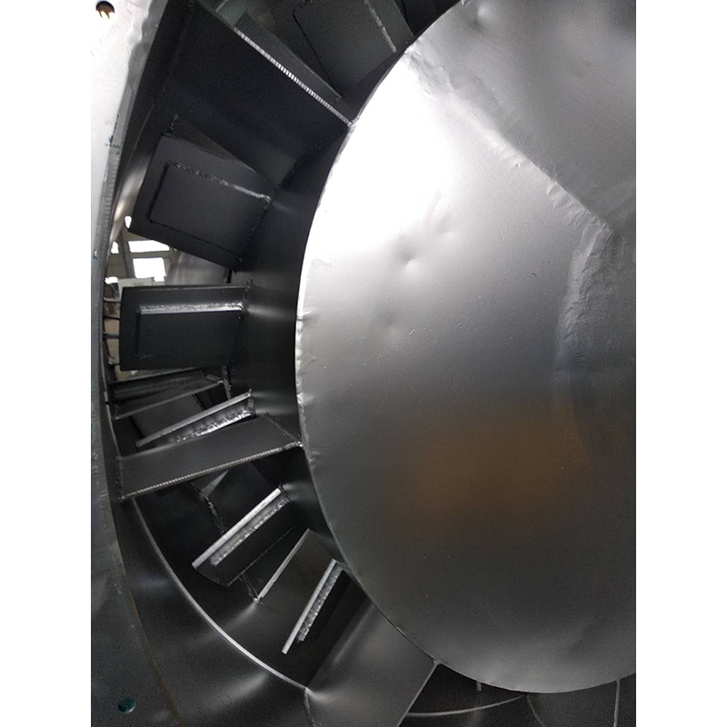
major Axial flow fan Common fault: the working medium of the fan in the cement industry often contains a certain amount of homogeneous particles with different sizes and shapes, such as the induced draft fan of the dust removal system and the blower for pneumatic conveying. Because these fans work in the dusty air flow, the dust particles in the air flow will not only wear the fan, but also attach ash on the fan blades, and the wear and ash deposition are uneven. As a result, the balance of the fan rotor is destroyed, which causes the fan vibration and shortens the life of the fan. In serious cases, the fan can not work normally. In particular, the fan blades are most severely worn, Axial flow fan manufactor It not only destroys the flow characteristics in the fan, but also easily leads to major accidents such as blade fracture and runaway. The wear of transmission parts is also a common problem of fans, including various shafts, rollers, reducers, motors, pumps and other bearing positions, bearing seats, keyways, threads and other parts. The traditional repair welding machine processing method is easy to cause material damage, resulting in deformation or fracture of parts, with greater limitations; Brush plating and spray re machining methods often require outsourcing, which not only requires long repair cycle and high cost, but also can not fundamentally solve the causes of wear (poor impact resistance and yield of metal) because the repair materials are metal materials; Many parts can only be scrapped and replaced, which greatly increases the production cost and inventory of spare parts, leaving the enterprise's good resource advantage idle and wasted

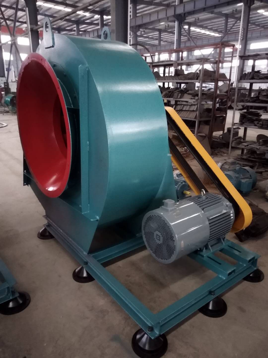
Axial flow fan manufactor The work starts before the fan is used. one Xiangyang Axial flow fan manufactor Carefully read the fan operation instructions and product samples, and be familiar with and understand the fan specifications, forms, impeller rotation direction and air flow in and out direction; Check whether all parts of the fan are in good condition again, or they can be installed and used only after being repaired. 2. The fan must be installed with safety devices to prevent accidents, and installed and wired by professionals familiar with relevant safety requirements. 3. The air duct connecting the inlet and outlet of the fan has separate support, and it is not allowed to add the overlapping weight of the duct to the components of the fan; When installing the fan, pay attention to the horizontal position of the fan, and adjust the connection between the joint surface of the fan and the foundation and the air outlet pipe to make it coincide naturally. Forced connection is not allowed. four major Axial flow fan After the fan is installed, move the impeller by hand or lever to check whether it is too tight or rubbed, and whether there is any object that hinders the rotation. The test run can be carried out only when there is no abnormal phenomenon. The exposed part of the fan transmission device should be equipped with a protective cover (provided by the user). If the fan inlet is not connected, a protective screen or other installation device (provided by the user) should also be added. 5. The power distribution control box of the fan must match the corresponding fan (power, voltage, pneumatic mode, control mode, etc.). 6. The fan wiring should be made by a professional electrician, and the wiring must be correct and reliable. Especially, the wiring number at the electric control box should be consistent with the number on the fan terminal. The fan shell should be reliably grounded. The grounding must be reliable, and zero connection cannot be used instead of grounding. 7. After all fans are installed, check whether there are any left tool box sundries inside the fan
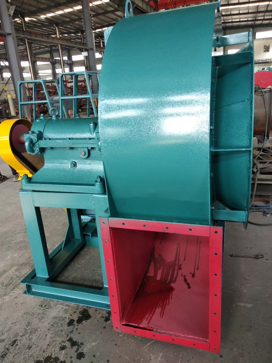
3. When installing Type C and Type B, ensure that the two pulley positions are on the same plane, and the flatness tolerance is 0.5mm. 4. When installing Type D, use a dial indicator and feeler gauge to measure the coaxiality of the fan spindle and motor spindle and the parallelism of both ends of the coupling. The coaxiality tolerance of two shafts is 0.2mm, the parallelism tolerance of both ends of the coupling is 0.2mm, and the spacing between two planes of the coupling is 5 to 8mm. 5. After the fan is installed, move the rotor with hand or lever to check whether it is too tight or collided. The test run can be carried out without overtightening or collision. 6. After the motor is installed, the belt pulley or coupling guard shall be installed. If the air inlet is not connected to the air inlet pipe, the guard net or other safety devices (provided by the user) shall also be provided. 7. Other parts shall be installed according to the corresponding positions in the drawing. 8. Add N46 (ISO VG46, 30) in summer and N32 (ISO VG32, 20) in winter. The oil level should be at 1/2 of the oil window.
When the bearing temperature of the fan is normal, it is ≤ 70 ℃. If it rises to 70 ℃, an alarm should (will) be given if there is an electric control. At this time, the reason should be found out. First, check whether the cooling water is normal? Is the bearing oil level normal? If the cause cannot be found for a while, the bearing temperature rises rapidly to 90 ℃, and if there is an electric control, the alarm and shutdown signal shall be sent again. Xiangyang Axial flow fan In the process of fan startup, shutdown or operation, if any abnormal phenomenon is found, it shall be checked immediately. If any small fault is found during the check, it shall be timely found out the cause and eliminated. In case of major fault (such as severe vibration, impact of fan, sharp rise of bearing temperature, etc.), stop the machine immediately for inspection. major Axial flow fan The lubricating oil (or grease) shall be renewed and replaced one month after the first operation of the fan. In addition to replacement after each overhaul, the lubricating oil (or grease) can be replaced once every 1~2 months under normal conditions, or according to the actual situation. Fans include fans, turbine blowers, roots blowers and turbine compressors, which are divided into 7 categories in detail, including centrifugal compressors, axial compressors, centrifugal blowers, roots blowers, centrifugal fans, axial fans and Ye's blowers
(3) The main faults and causes of the fan may occur during the operation of the fan. For the faults generated, the causes must be quickly identified and solved in time to prevent accidents. Faults in the Operation of 4-72-12 Centrifugal Fan and the Causes Table Fault Name Causes Severe Vibration of Bearing Box 1. The fan shaft is different from the motor shaft, and the coupling is installed askew. 2. The casing or air inlet rubs with the impeller. 3. The foundation stiffness is not enough or firm. 4. Impeller rivet is loose or wheel disc is deformed. 5. The impeller shaft disk and shaft are loose, and the coupling bolt is movable. 6. The connection between casing and bracket, bearing box and bracket, bearing box and seat is loose. 7. The air inlet and outlet pipes of the fan are poorly installed, causing vibration. 8. The rotor is unbalanced. Bearing temperature rise is too high 1. The bearing box vibrates violently. 2. The lubricating grease is poor in quality, deteriorated or overfilled, or contains dust, sand, dirt and other impurities. 3. The tightening force of connecting bolts of bearing cover seat is too large or too small. 4. The shaft and rolling bearing are installed askew, and the front and rear bearings are not concentric. 5. The rolling bearing is damaged. The motor current is too high and the temperature rise is too high. 1. The throttle valve in the air inlet pipe is not closed tightly when driving. 2. The flow exceeds the specified value, or the air duct leaks. 3. The gas density conveyed by the fan is too high. 4. The input voltage of the motor is too low or the power supply is cut off individually. 5. The coupling is improperly connected, the leather ring is too tight or the gap is uneven. 6. Affected by the violent vibration of the bearing box. 7. Affected by deterioration or failure of parallel fans. When the belt slides down, the two pulleys are not in the same plane with each other. Belt runout The distance between two pulleys is too close or the belt is too long.


