Selection and application of fan performance (I) Description of fan performance: 1. № 10, 12, 16, 20 are converted according to dimensionless performance of № 10 model. 2. № 5, 6, 8 are converted according to dimensionless performance of № 5 model. 3. № 5 and below shall be determined according to the performance of the measured prototype. Note: According to the dimensionless performance curve conversion formula, total pressure H=ρ u2 H (Pa) flow Q=900 π D22 uQ (m3/h) shaft power N=N × D22u3 ρ/4000 (kw), where D2 - impeller outer diameter (m) u - impeller outer edge linear speed (m/s) ρ - gas density (Kg/m3), the required power rate shall be based on shaft power plus mechanical loss and motor reserve. 4. The solid line is № 5 model, and the dotted line is № 10 model. The performance of the fan is expressed by the flow, total pressure, main shaft speed, shaft power, efficiency and other parameters of the fan, and there are certain relationships between the parameters, which are listed in the following table. The relationship of fan performance parameters changes density ρ, speed n changes speed n, atmospheric pressure P, gas temperature t Q1/Q2=n1/n2 H1/H2=(n1/n2) 2 ρ 1/ρ 2 N1/N2=(n1/n2) 3 ρ 1/ρ 2 η 1=η 2 Q1/Q2=n1/n2 H1/H2=(n1/n2) 2 (P1/P2) (273+t2/273+t1) N1/N2=(n1/n2) 3 (P1/P2) (273+t2/273+t1) η 1=η 2 Note: 1. In the middle, Q represents flow (m3/h), H represents total pressure (Pa), N represents shaft power (kw), η represents full pressure efficiency, ρ represents density (kg/m3), t represents temperature (℃), n represents speed (r/min), and P represents atmospheric pressure (Pa). 2. The footnote symbol 2 indicates the known performance and related parameters, and the footnote symbol 1 indicates the required performance and related parameters. (
(2) Precautions for normal operation of fan 1. If the flow is found to be too large, which does not meet the operating requirements, or less flow is required in a short time, the throttling device can be used to adjust to meet the operating requirements. 2. The sensitivity of thermometer and oil pointer shall be checked regularly. 3. In case of any abnormal phenomenon during the start-up, shutdown or operation of the fan, it shall be checked in time. 4. For minor faults found in the inspection, find out the causes in time and try to eliminate or deal with them. If minor faults cannot be eliminated or major faults are found, repair them immediately. 5. In addition to replacing the lubricating oil during each maintenance, the lubricating oil shall also be replaced regularly. Observe the oil level at ordinary times and replenish lubricating oil in time.
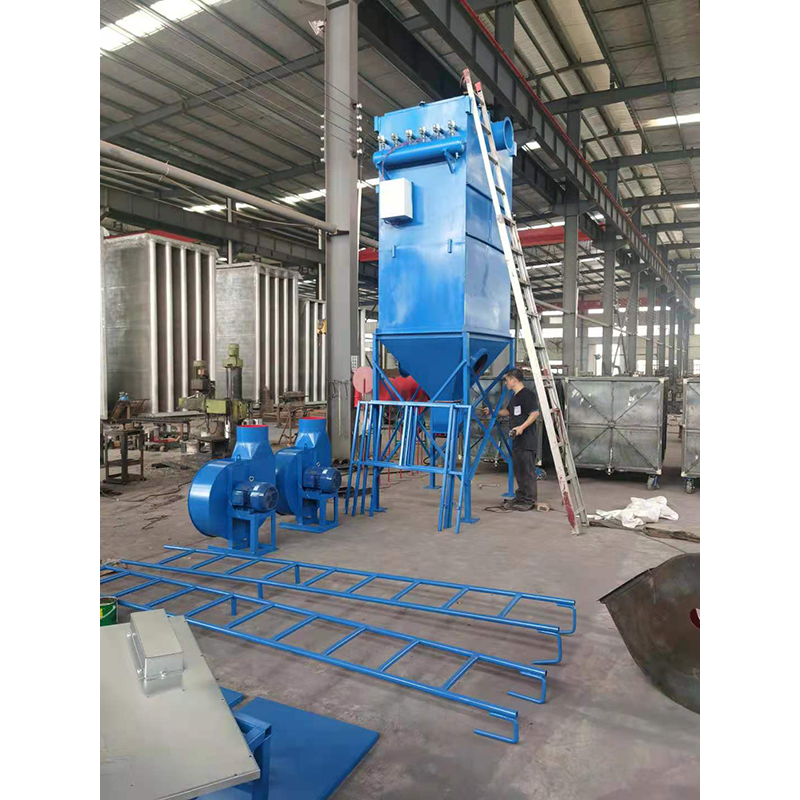
Dust leakage may occur when the wet electrostatic precipitator is used at ordinary times, so that the precipitator can not achieve the expected use effect when it is used Wet dedusting company Let's specifically analyze the causes of dust leakage. 1. The dust remover is mainly assembled from the clean air chamber and the hopper. In this part, screws are used at the connection position between the upper box and the hopper. If the sealing strip used in this place is unqualified, dust will leak out. In addition to affecting the normal use of the equipment, the poor performance of the dust remover in use will have a great impact on the environment of the whole workshop and the surrounding environment. Even some wet electrostatic precipitators have a lot of materials with recycling value in the recycled dust. two Zhengzhou large Wet dedusting Improper filtering wind speed used in dedusting may also lead to dust leakage, because the dust will be adsorbed on the filter bag when the temperature is too high, so the resistance of dedusting equipment will increase when it is used, leading to leakage. 3. The dedusting bag is also a device that plays a major role in the operation and use of the equipment. If the density of the bag itself is relatively small, it may cause dust leakage to each other. Therefore, when selecting the bag, it is also necessary to select the one with better quality for use, and it is also necessary to do a good job of maintenance when using it again.
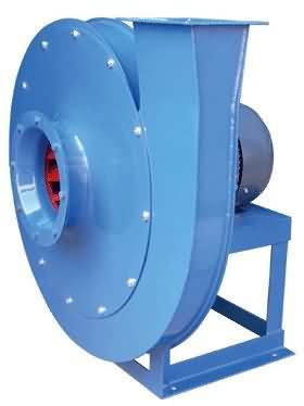
(3) The main faults and causes of the fan may occur during the operation of the fan. For the faults generated, the causes must be quickly identified and solved in time to prevent accidents. Faults in the Operation of 4-72-12 Centrifugal Fan and the Causes Table Fault Name Causes Severe Vibration of Bearing Box 1. The fan shaft is different from the motor shaft, and the coupling is installed askew. 2. The casing or air inlet rubs with the impeller. 3. The foundation stiffness is not enough or firm. 4. Impeller rivet is loose or wheel disc is deformed. 5. The impeller shaft disk and shaft are loose, and the coupling bolt is movable. 6. The connection between casing and bracket, bearing box and bracket, bearing box and seat is loose. 7. The air inlet and outlet pipes of the fan are poorly installed, causing vibration. 8. The rotor is unbalanced. Bearing temperature rise is too high 1. The bearing box vibrates violently. 2. The lubricating grease is poor in quality, deteriorated or overfilled, or contains dust, sand, dirt and other impurities. 3. The tightening force of connecting bolts of bearing cover seat is too large or too small. 4. The shaft and rolling bearing are installed askew, and the front and rear bearings are not concentric. 5. The rolling bearing is damaged. The motor current is too high and the temperature rise is too high. 1. The throttle valve in the air inlet pipe is not closed tightly when driving. 2. The flow exceeds the specified value, or the air duct leaks. 3. The gas density conveyed by the fan is too high. 4. The input voltage of the motor is too low or the power supply is cut off individually. 5. The coupling is improperly connected, the leather ring is too tight or the gap is uneven. 6. Affected by the violent vibration of the bearing box. 7. Affected by deterioration or failure of parallel fans. When the belt slides down, the two pulleys are not in the same plane with each other. Belt runout The distance between two pulleys is too close or the belt is too long.
How are dust collectors classified, large Wet dedusting Do you know how to distinguish it and how to define its economic type? Let's talk about it from these aspects. 1. Dust removal efficiency. Zhengzhou Wet dedusting Dust removal efficiency refers to the ratio of the amount of dust collected by the dust collector to the amount of dust entering the dust collector. According to the total dedusting efficiency, the dedusters can be divided into: low efficiency dedusters (50~80%), medium efficiency dedusters (80~95%) and high efficiency dedusters (more than 95%). 2. Dust removal resistance. The resistance indicates the pressure loss when the airflow passes through the dust remover. According to the resistance, dust collectors can be divided into low resistance dust collectors (Δ P<500Pa), medium resistance dust collectors (Δ P=500 ~ 2000Pa) and high resistance dust collectors (Δ P=2000 ~ 20000Pa). 3. Economy. Economy is one of the important indexes for evaluating dust remover, which includes equipment cost and operation and maintenance cost of dust remover. Among all kinds of dust collectors, the equipment cost of electrostatic precipitator is the highest, followed by bag type dust collector, Venturi tube dust collector, cyclone dust collector is the lowest electrostatic precipitator: the dust removal efficiency is high, generally above 99%, and the design efficiency is up to 99.99%. The wet dust collector is commonly known as "water dust collector" : The filtration efficiency can reach more than 85%, and the integrated desulfurization and dust remover of stone water film+swirl plate>>about 80% of desulfurization and dust removal can reach as high as about 95%.
2. The influence of the total pressure deviation Δ H of the fan itself was not considered during selection. When the actual total pressure of the fan was positive deviation, the flow increased; When the actual total pressure of the fan is negative deviation, the flow decreases. See (a) below. The relationship between the deviation of the pipe network characteristic curve and the total pressure and the flow can be eliminated by one of the following methods when the fan starts to officially operate after new installation, or when the flow is too large or too small during use. 1. Use the opening and closing of throttling device to adjust the flow. 2. Increase or decrease the flow by increasing or decreasing the fan speed. 3. Use a new fan with higher or lower pressure to increase or decrease the flow. 4. Change the pipe network to reduce the resistance coefficient of the pipe network to increase the flow. It must be pointed out that throttling devices are generally used to regulate the flow. However, when the actual flow is much larger than the required flow, this method wastes too much power and is very uneconomical. If conditions permit, the fan speed is usually reduced or the fan with lower pressure is replaced. When the throttling device is fully open, the flow is still too small. At this time, the throttling device has lost its function, so try to reduce the resistance coefficient of the pipe network to increase the flow, or increase the fan speed and replace the fan with higher pressure. However, the speed of the fans directly connected to the motor and the coupling cannot be changed generally. Only the fan driven by the pulley can increase or decrease the speed by changing the diameter of the pulley, but the speed of the fan cannot exceed the speed max in the performance and selection table.


