Wet dust remover is a device that uses the action of water or other liquids and dusty gases to remove dust particles. When dust particles meet with sprayed water droplets, water films or wetted walls and devices The process of wetting, condensation, diffusion and sedimentation takes place, so it is separated from the gas to purify the gas. Yichang Axial flow fan Price It is characterized by purifying dust at the same time It can also purify gas, customized Axial flow fan When the flue gas contains combustible components, the use of wet dust collectors can avoid equipment explosion, and the dust removal effect can generally meet the environmental protection requirements. The equipment is small and the investment is relatively low. Therefore, there are three wet dust collectors used in dust removal projects in mining, metallurgy, machinery, light industry, building materials and other industries. Sludge containing sewage must be treated, otherwise secondary pollution may occur, Therefore, it is not widely used as dry dust collector. There are many types of wet dust collectors. According to their structures, there are the following types: ① gravity spray wet dust collectors - spray scrubbing towers; ② Cyclone wet dust collector - cyclone water film dust collector, water film dust collector; ③ Self excited wet dust collector - impulse dust collector, water bath dust collector; ④ Packed wet dust collector - packed tower, turbulent ball tower; ⑤ Foam wet dust collector - foam dust collector Cyclone dust collector, leaky plate tower; ⑥ Venturi wet dust collector - Venturi tube dust collector; ⑦ Mechanical induction wet dust collector - water wheel dust collector.
Axial flow fan Price The work starts before the fan is used. one Yichang Axial flow fan Price Carefully read the fan operation instructions and product samples, and be familiar with and understand the fan specifications, forms, impeller rotation direction and air flow in and out direction; Check whether all parts of the fan are in good condition again, or they can be installed and used only after being repaired. 2. The fan must be installed with safety devices to prevent accidents, and installed and wired by professionals familiar with relevant safety requirements. 3. The air duct connecting the inlet and outlet of the fan has separate support, and it is not allowed to add the overlapping weight of the duct to the components of the fan; When installing the fan, pay attention to the horizontal position of the fan, and adjust the connection between the joint surface of the fan and the foundation and the air outlet pipe to make it coincide naturally. Forced connection is not allowed. four customized Axial flow fan After the fan is installed, move the impeller by hand or lever to check whether it is too tight or rubbed, and whether there is any object that hinders the rotation. The test run can be carried out only when there is no abnormal phenomenon. The exposed part of the fan transmission device should be equipped with a protective cover (provided by the user). If the fan inlet is not connected, a protective screen or other installation device (provided by the user) should also be added. 5. The power distribution control box of the fan must match the corresponding fan (power, voltage, pneumatic mode, control mode, etc.). 6. The fan wiring should be made by a professional electrician, and the wiring must be correct and reliable. Especially, the wiring number at the electric control box should be consistent with the number on the fan terminal. The fan shell should be reliably grounded. The grounding must be reliable, and zero connection cannot be used instead of grounding. 7. After all fans are installed, check whether there are any left tool box sundries inside the fan
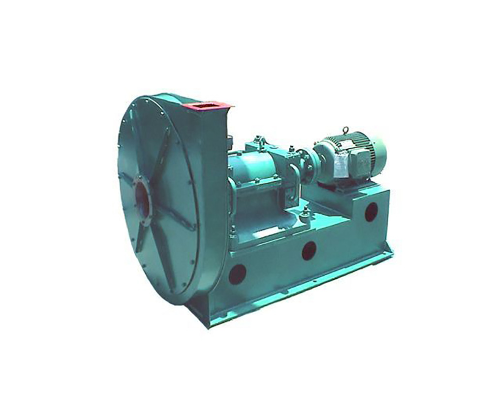
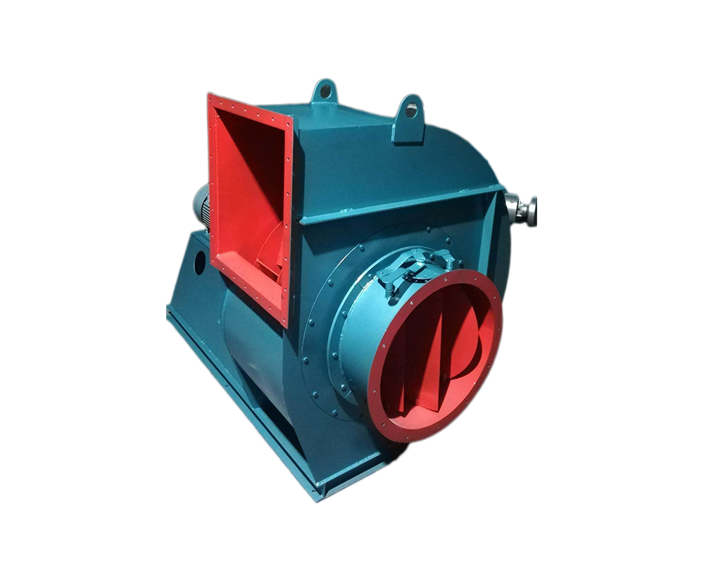
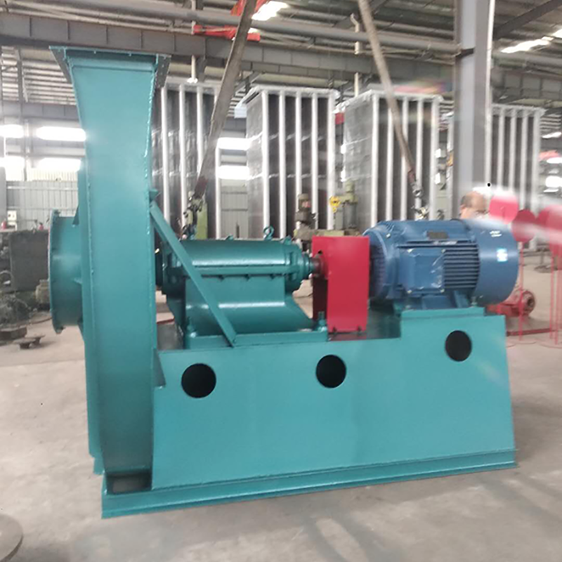
customized Axial flow fan Fans can be divided into axial flow fans, centrifugal fans and diagonal flow (mixed flow) fans according to the flow direction after the airflow enters the impeller. Fans are divided into press in local fans (hereinafter referred to as press in fans) and flame-proof motors placed outside or inside the flow channel, and flame-proof motors placed inside the explosion-proof sealing chamber of the extraction type local fans (hereinafter referred to as extraction fans) according to their purposes. Axial flow fan Price Fans can also be divided into single-stage, two-stage or multi-stage pressurization fans according to the form of pressurization. For example, 4-72 is single-stage pressurization, and high-end fan is multi-stage pressurization fan. Fans can be divided into axial flow fans, mixed flow fans, roof fans, air conditioning fans, etc. Fan can be divided into negative pressure fan, low pressure fan, medium pressure fan and high pressure fan according to pressure. According to the outlet pressure (pressure rise), it can be divided into: ventilator (≤ 15000 Pa), blower (15-350000 Pa), compressor (≥ 350000 Pa)
Selection and application of fan performance (I) Description of fan performance: 1. № 10, 12, 16, 20 are converted according to dimensionless performance of № 10 model. 2. № 5, 6, 8 are converted according to dimensionless performance of № 5 model. 3. № 5 and below shall be determined according to the performance of the measured prototype. Note: According to the dimensionless performance curve conversion formula, total pressure H=ρ u2 H (Pa) flow Q=900 π D22 uQ (m3/h) shaft power N=N × D22u3 ρ/4000 (kw), where D2 - impeller outer diameter (m) u - impeller outer edge linear speed (m/s) ρ - gas density (Kg/m3), the required power rate shall be based on shaft power plus mechanical loss and motor reserve. 4. The solid line is № 5 model, and the dotted line is № 10 model. The performance of the fan is expressed by the flow, total pressure, main shaft speed, shaft power, efficiency and other parameters of the fan, and there are certain relationships between the parameters, which are listed in the following table. The relationship of fan performance parameters changes density ρ, speed n changes speed n, atmospheric pressure P, gas temperature t Q1/Q2=n1/n2 H1/H2=(n1/n2) 2 ρ 1/ρ 2 N1/N2=(n1/n2) 3 ρ 1/ρ 2 η 1=η 2 Q1/Q2=n1/n2 H1/H2=(n1/n2) 2 (P1/P2) (273+t2/273+t1) N1/N2=(n1/n2) 3 (P1/P2) (273+t2/273+t1) η 1=η 2 Note: 1. In the middle, Q represents flow (m3/h), H represents total pressure (Pa), N Represents shaft power (kw), η represents total pressure efficiency, ρ represents density (kg/m3), t represents temperature (℃), n represents speed (r/min), and P represents atmospheric pressure (Pa). 2. The footnote symbol 2 indicates the known performance and related parameters, and the footnote symbol 1 indicates the required performance and related parameters. (


