Forecast from domestic market capacity. Huangshi Axial flow centrifugal fan manufactor Fans vary greatly according to different pressure and flow requirements. Therefore, the fan demand should be differentiated according to its type and size, and predicted according to the demand of different industries. According to incomplete statistics, the annual average growth rate of national fan output was 13.8% from 1980 to 1996. major Axial flow centrifugal fan It is estimated that the total output of wind turbines in China will be 2.6 million to 2.9 million in 2005 and 3.1 million to 3.25 million in 2010. According to the statistics of fan industry over the years, it is predicted that the output of centrifugal compressors will be 1.6 million to 1.8 million in 2005 and 2 million to 2.1 million in 2010; The output of axial compressor is 260000 in 2005, and is expected to reach 360000 in 2010; The market share of turbine compressor and blower will reach about 70% in 2005
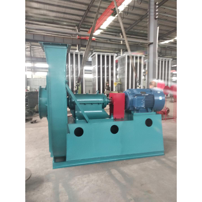
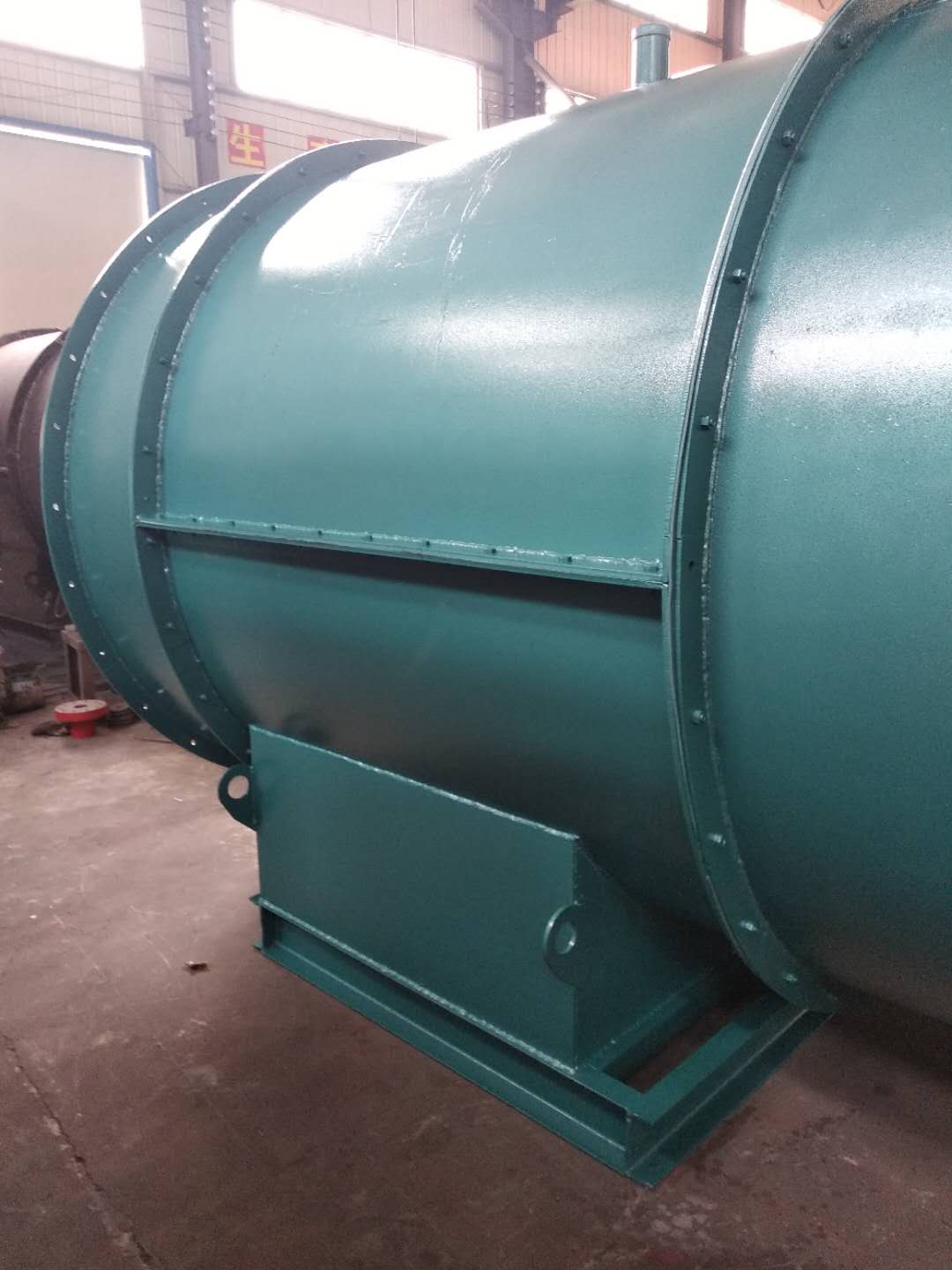
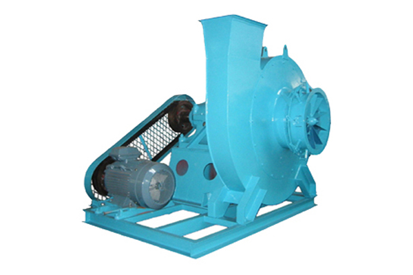
Huangshi Axial flow centrifugal fan Classified by layers. There are many classification methods for fans, which can be roughly classified according to the following levels: (1) According to the level of pressure generated, they can be divided into: volumetric: reciprocating and rotary; Turbine type: centrifugal, axial flow, mixed flow and cross flow, jet type. Fan generally refers to turbine type, namely centrifugal, axial, mixed flow, cross flow and other forms. Its main characteristics are: centrifugal fan: higher pressure, but smaller air volume. Axial flow fan: higher air volume, but lower pressure. Mixed flow fan: the air volume and pressure are between centrifugal fan and axial fan. Horizontal fan: with high dynamic pressure, it can obtain flat airflow. (2) major Axial flow centrifugal fan According to the different materials used, it can be divided into:; Iron shell fan (ordinary fan), glass fiber reinforced plastic fan, plastic fan, aluminum fan, stainless steel fan, etc. (3) According to the direction of gas flow, it can be divided into centrifugal type, axial flow type, diagonal flow type (mixed flow type) and cross flow type. (4) According to the flow direction of the airflow entering the impeller, it can be divided into axial flow fan, centrifugal fan and diagonal flow (mixed flow) fan. (5) Axial flow centrifugal fan manufactor It can be divided into: press in local fans and flame-proof motors placed outside or inside the flow channel, and flame-proof motors placed inside the explosion-proof sealing chamber of the extraction type local fans. (6) According to the form of pressurization, it can also be divided into single-stage, two-stage or multi-stage pressurization fans
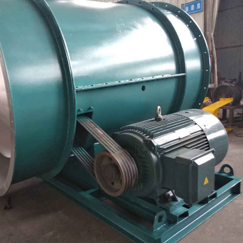
2. The influence of the total pressure deviation Δ H of the fan itself was not considered during selection. When the actual total pressure of the fan was positive deviation, the flow increased; When the actual total pressure of the fan is negative deviation, the flow decreases. See (a) below. The relationship between the deviation of the pipe network characteristic curve and the total pressure and the flow can be eliminated by one of the following methods when the fan starts to officially operate after new installation, or when the flow is too large or too small during use. 1. Use the opening and closing of throttling device to adjust the flow. 2. Increase or decrease the flow by increasing or decreasing the fan speed. 3. Use a new fan with higher or lower pressure to increase or decrease the flow. 4. Change the pipe network to reduce the resistance coefficient of the pipe network to increase the flow. It must be pointed out that throttling devices are generally used to regulate the flow. However, when the actual flow is much larger than the required flow, this method wastes too much power and is very uneconomical. If conditions permit, the fan speed is usually reduced or the fan with lower pressure is replaced. When the throttling device is fully open, the flow is still too small. At this time, the throttling device has lost its function, so try to reduce the resistance coefficient of the pipe network to increase the flow, or increase the fan speed and replace the fan with higher pressure. However, the speed of the fans directly connected to the motor and the coupling cannot be changed generally. Only the fan driven by the pulley can increase or decrease the speed by changing the diameter of the pulley, but the speed of the fan cannot exceed the speed max in the performance and selection table.
Selection and application of fan performance (I) Description of fan performance: 1. № 10, 12, 16, 20 are converted according to dimensionless performance of № 10 model. 2. № 5, 6, 8 are converted according to dimensionless performance of № 5 model. 3. № 5 and below shall be determined according to the performance of the measured prototype. Note: According to the dimensionless performance curve conversion formula, total pressure H=ρ u2 H (Pa) flow Q=900 π D22 uQ (m3/h) shaft power N=N × D22u3 ρ/4000 (kw), where D2 - impeller outer diameter (m) u - impeller outer edge linear speed (m/s) ρ - gas density (Kg/m3), the required power rate shall be based on shaft power plus mechanical loss and motor reserve. 4. The solid line is № 5 model, and the dotted line is № 10 model. The performance of the fan is expressed by the flow, total pressure, main shaft speed, shaft power, efficiency and other parameters of the fan, and there are certain relationships between the parameters, which are listed in the following table. The relationship of fan performance parameters changes density ρ, speed n changes speed n, atmospheric pressure P, gas temperature t Q1/Q2=n1/n2 H1/H2=(n1/n2) 2 ρ 1/ρ 2 N1/N2=(n1/n2) 3 ρ 1/ρ 2 η 1=η 2 Q1/Q2=n1/n2 H1/H2=(n1/n2) 2 (P1/P2) (273+t2/273+t1) N1/N2=(n1/n2) 3 (P1/P2) (273+t2/273+t1) η 1=η 2 Note: 1. In the middle, Q represents flow (m3/h), H represents total pressure (Pa), N Represents shaft power (kw), η represents total pressure efficiency, ρ represents density (kg/m3), t represents temperature (℃), n represents speed (r/min), and P represents atmospheric pressure (Pa). 2. The footnote symbol 2 indicates the known performance and related parameters, and the footnote symbol 1 indicates the required performance and related parameters. (