(2) Precautions for normal operation of fan 1. If the flow is found to be too large, which does not meet the operating requirements, or less flow is required in a short time, the throttling device can be used to adjust to meet the operating requirements. 2. The sensitivity of thermometer and oil pointer shall be checked regularly. 3. In case of any abnormal phenomenon during the start-up, shutdown or operation of the fan, it shall be checked in time. 4. For minor faults found in the inspection, find out the causes in time and try to eliminate or deal with them. If minor faults cannot be eliminated or major faults are found, repair them immediately. 5. In addition to replacing the lubricating oil during each maintenance, the lubricating oil shall also be replaced regularly. Observe the oil level at ordinary times and replenish lubricating oil in time.
The wet electrostatic precipitator has been recognized by users due to many advantages in the process of application. It can remove dust and purify waste gas. It is an environmental protection equipment that can be used in a wide range of situations. What steps can we take when using this environmental protection equipment? today Wet electrostatic precipitator company Let's take a detailed look. 1. First, close the power switch of the wet electrostatic precipitator. When the power indicator is on, the local remote switch will be switched to the local position; 2. Press the fan start button, and then observe whether the fan of the wet electrostatic precipitator rotates correctly. After the fan rotates normally, normal dedusting operation can be started; 3、 large Wet electrostatic precipitator After a period of time, if you need to clear and discharge the ash, you can press the ash cleaning button on the wet electrostatic precipitator; 4. Turn over the pulse valve to clear the ash, and the screw machine and ash discharge valve will also work together. The above is the whole content of the application process of the wet electrostatic precipitator. What we need to remind us here is that the equipment can be started only after the position is adjusted before it is used. During the dust removal process of the equipment, the humidification function can be started to keep the ground wet, so that the wet electrostatic precipitator can have a better application effect.
Wet electrostatic precipitator company Different types of dust remover equipment have their own precautions. When we usually use the dust remover equipment, we should tell my customer friends some application matters. What matters should we consider when using wet electrostatic precipitator? Matters needing attention on the application of wet electrostatic precipitator. 1. The wet electrostatic precipitator shall be put into the insulator chamber electric heating and hot air purging system at least 8 hours in advance to ensure that the temperature of the insulator chamber is more than 60 ℃. 2. The wet desulfurization system of the wet electrostatic precipitator is put into operation early to prevent dry and high-temperature smoke from entering the wet electrostatic precipitator, which will lead to scaling of internal parts and damage of internal anti-corrosion coating. three large Wet electrostatic precipitator The wet dust collector can be opened when the following three conditions are met together: 3.1 The wet electrostatic precipitator is operated with 25% of the oil gun remaining and 35% of the powder feeding is normal and stable or the oil gun is completely withdrawn. 3.2 The temperature of flue gas entering the wet electrostatic precipitator is lower than 70 ℃. 3.3 Desulfurization equipment has been opened. 4. The process of opening the wet electrostatic precipitator: first open the low-pressure water supply system and then the high-pressure power supply system.
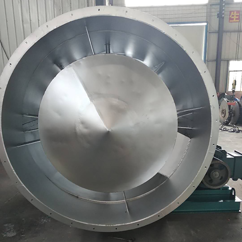
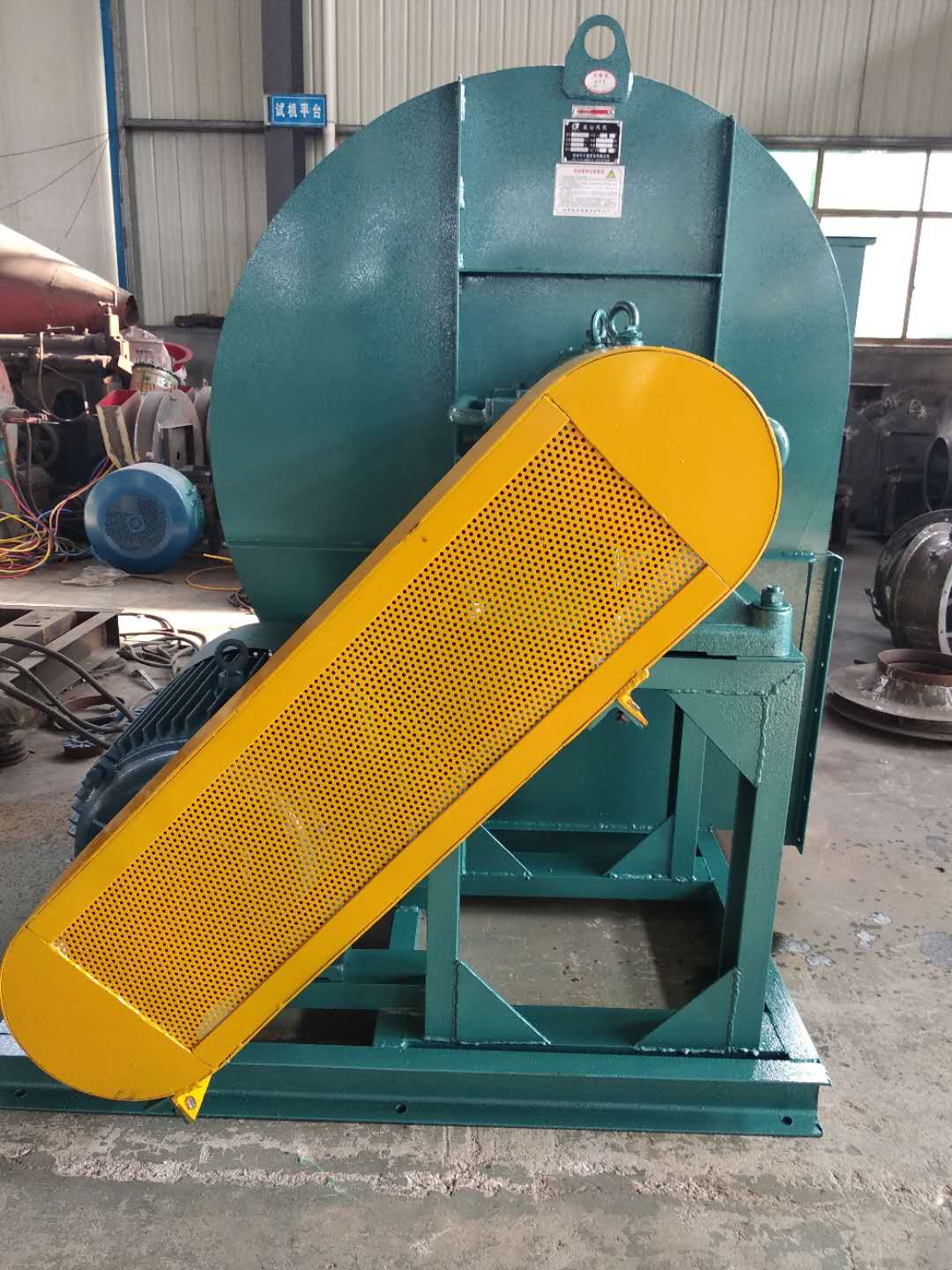
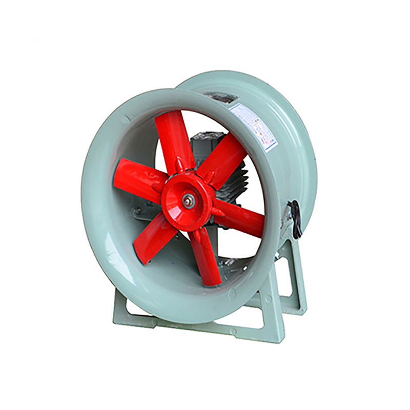
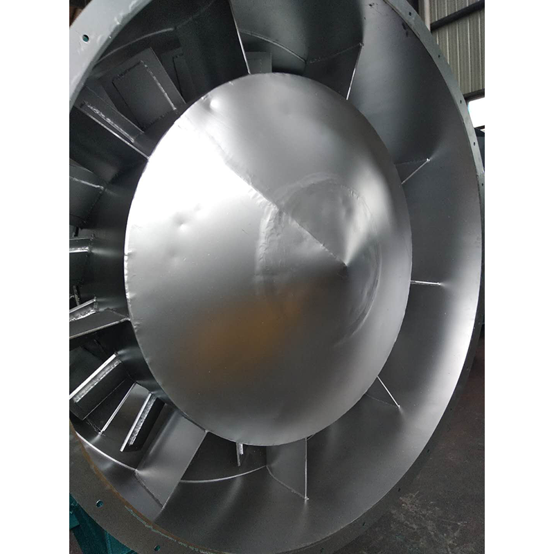
Fans can be classified into several types according to the materials used, such as iron shell fans (ordinary fans), glass fiber reinforced plastic fans, plastic fans, aluminum fans, stainless steel fans, etc. Wet electrostatic precipitator company In the direction of gas flow. Fans can be classified into centrifugal, axial, diagonal (mixed flow) and cross flow fans according to the direction of gas flow. (1) Centrifugal fan. The airflow enters the impeller of the fan axially and flows mainly along the radial direction. This type of fan is made according to the principle of centrifugal action, and its products include centrifugal fan, centrifugal blower and centrifugal compressor. (2) Axial flow fan. The airflow enters the impeller of the fan axially and flows approximately along the axis on the cylindrical surface. Such fans include axial fans, axial blowers and axial compressors. (3) Rotary fan. Huangshi large Wet electrostatic precipitator Use the rotor rotation to change the air chamber volume to work. Common varieties include Roots blower and rotary compressor.
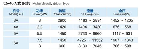
Selection and application of fan performance (I) Description of fan performance: 1. № 10, 12, 16, 20 are converted according to dimensionless performance of № 10 model. 2. № 5, 6, 8 are converted according to dimensionless performance of № 5 model. 3. № 5 and below shall be determined according to the performance of the measured prototype. Note: According to the dimensionless performance curve conversion formula, total pressure H=ρ u2 H (Pa) flow Q=900 π D22 uQ (m3/h) shaft power N=N × D22u3 ρ/4000 (kw), where D2 - impeller outer diameter (m) u - impeller outer edge linear speed (m/s) ρ - gas density (Kg/m3), the required power rate shall be based on shaft power plus mechanical loss and motor reserve. 4. The solid line is № 5 model, and the dotted line is № 10 model. The performance of the fan is expressed by the flow, total pressure, main shaft speed, shaft power, efficiency and other parameters of the fan, and there are certain relationships between the parameters, which are listed in the following table. The relationship of fan performance parameters changes density ρ, speed n changes speed n, atmospheric pressure P, gas temperature t Q1/Q2=n1/n2 H1/H2=(n1/n2) 2 ρ 1/ρ 2 N1/N2=(n1/n2) 3 ρ 1/ρ 2 η 1=η 2 Q1/Q2=n1/n2 H1/H2=(n1/n2) 2 (P1/P2) (273+t2/273+t1) N1/N2=(n1/n2) 3 (P1/P2) (273+t2/273+t1) η 1=η 2 Note: 1. In the middle, Q represents flow (m3/h), H represents total pressure (Pa), N Represents shaft power (kw), η represents total pressure efficiency, ρ represents density (kg/m3), t represents temperature (℃), n represents speed (r/min), and P represents atmospheric pressure (Pa). 2. The footnote symbol 2 indicates the known performance and related parameters, and the footnote symbol 1 indicates the required performance and related parameters. (