How are dust collectors classified, customized Industrial dust collector Do you know how to distinguish it and how to define its economic type? Let's talk about it from these aspects. 1. Dust removal efficiency. Southwest Guizhou Industrial dust collector Dust removal efficiency refers to the ratio of the amount of dust collected by the dust collector to the amount of dust entering the dust collector. According to the total dedusting efficiency, the dedusters can be divided into: low efficiency dedusters (50~80%), medium efficiency dedusters (80~95%) and high efficiency dedusters (more than 95%). 2. Dust removal resistance. The resistance indicates the pressure loss when the airflow passes through the dust remover. According to the resistance, dust collectors can be divided into low resistance dust collectors (Δ P<500Pa), medium resistance dust collectors (Δ P=500 ~ 2000Pa) and high resistance dust collectors (Δ P=2000 ~ 20000Pa). 3. Economy. Economy is one of the important indexes for evaluating dust remover, which includes equipment cost and operation and maintenance cost of dust remover. Among all kinds of dust collectors, the equipment cost of electrostatic precipitator is the highest, followed by bag type dust collector, Venturi tube dust collector, cyclone dust collector is the lowest electrostatic precipitator: the dust removal efficiency is high, generally above 99%, and the design efficiency is up to 99.99%. The wet dust collector is commonly known as "water dust collector" : The filtration efficiency can reach more than 85%, and the integrated desulfurization and dust remover of stone water film+swirl plate>>about 80% of desulfurization and dust removal can reach as high as about 95%.
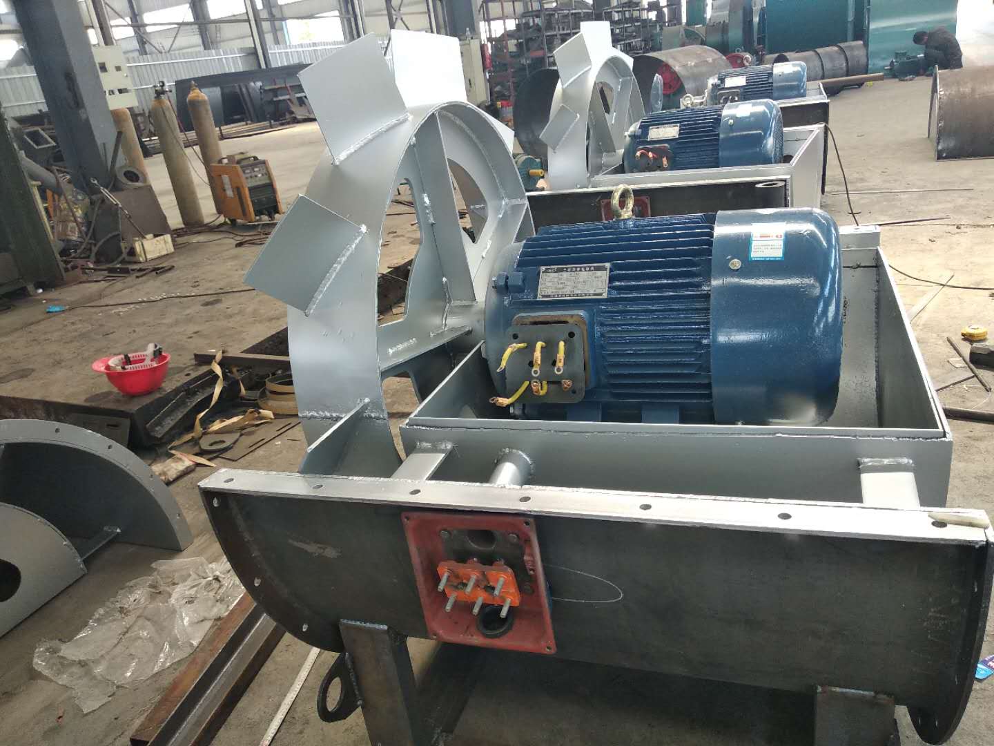
Industrial dust collector manufactor The work starts before the fan is used. one Southwest Guizhou Industrial dust collector manufactor Carefully read the fan operation instructions and product samples, and be familiar with and understand the fan specifications, forms, impeller rotation direction and air flow in and out direction; Check whether all parts of the fan are in good condition again, or they can be installed and used only after being repaired. 2. The fan must be installed with safety devices to prevent accidents, and installed and wired by professionals familiar with relevant safety requirements. 3. The air duct connecting the inlet and outlet of the fan has separate support, and it is not allowed to add the overlapping weight of the duct to the components of the fan; When installing the fan, pay attention to the horizontal position of the fan, and adjust the connection between the joint surface of the fan and the foundation and the air outlet pipe to make it coincide naturally. Forced connection is not allowed. four customized Industrial dust collector After the fan is installed, move the impeller by hand or lever to check whether it is too tight or rubbed, and whether there is any object that hinders the rotation. The test run can be carried out only when there is no abnormal phenomenon. The exposed part of the fan transmission device should be equipped with a protective cover (provided by the user). If the fan inlet is not connected, a protective screen or other installation device (provided by the user) should also be added. 5. The power distribution control box of the fan must match the corresponding fan (power, voltage, pneumatic mode, control mode, etc.). 6. The fan wiring should be made by a professional electrician, and the wiring must be correct and reliable. Especially, the wiring number at the electric control box should be consistent with the number on the fan terminal. The fan shell should be reliably grounded. The grounding must be reliable, and zero connection cannot be used instead of grounding. 7. After all fans are installed, check whether there are any left tool box sundries inside the fan
3. When installing Type C and Type B, ensure that the two pulley positions are on the same plane, and the flatness tolerance is 0.5mm. 4. When installing Type D, use a dial indicator and feeler gauge to measure the coaxiality of the fan spindle and motor spindle and the parallelism of both ends of the coupling. The coaxiality tolerance of two shafts is 0.2mm, the parallelism tolerance of both ends of the coupling is 0.2mm, and the spacing between two planes of the coupling is 5 to 8mm. 5. After the fan is installed, move the rotor with hand or lever to check whether it is too tight or collided. The test run can be carried out without overtightening or collision. 6. After the motor is installed, the belt pulley or coupling guard shall be installed. If the air inlet is not connected to the air inlet pipe, the guard net or other safety devices (provided by the user) shall also be provided. 7. Other parts shall be installed according to the corresponding positions in the drawing. 8. Add N46 (ISO VG46, 30) in summer and N32 (ISO VG32, 20) in winter. The oil level should be at 1/2 of the oil window.
Selection and application of fan performance (I) Description of fan performance: 1. № 10, 12, 16, 20 are converted according to dimensionless performance of № 10 model. 2. № 5, 6, 8 are converted according to dimensionless performance of № 5 model. 3. № 5 and below shall be determined according to the performance of the measured prototype. Note: According to the dimensionless performance curve conversion formula, total pressure H=ρ u2 H (Pa) flow Q=900 π D22 uQ (m3/h) shaft power N=N × D22u3 ρ/4000 (kw), where D2 - impeller outer diameter (m) u - impeller outer edge linear speed (m/s) ρ - gas density (Kg/m3), the required power rate shall be based on shaft power plus mechanical loss and motor reserve. 4. The solid line is № 5 model, and the dotted line is № 10 model. The performance of the fan is expressed by the flow, total pressure, main shaft speed, shaft power, efficiency and other parameters of the fan, and there are certain relationships between the parameters, which are listed in the following table. The relationship of fan performance parameters changes density ρ, speed n changes speed n, atmospheric pressure P, gas temperature t Q1/Q2=n1/n2 H1/H2=(n1/n2) 2 ρ 1/ρ 2 N1/N2=(n1/n2) 3 ρ 1/ρ 2 η 1=η 2 Q1/Q2=n1/n2 H1/H2=(n1/n2) 2 (P1/P2) (273+t2/273+t1) N1/N2=(n1/n2) 3 (P1/P2) (273+t2/273+t1) η 1=η 2 Note: 1. In the middle, Q represents flow (m3/h), H represents total pressure (Pa), N Represents shaft power (kw), η represents total pressure efficiency, ρ represents density (kg/m3), t represents temperature (℃), n represents speed (r/min), and P represents atmospheric pressure (Pa). 2. The footnote symbol 2 indicates the known performance and related parameters, and the footnote symbol 1 indicates the required performance and related parameters. (
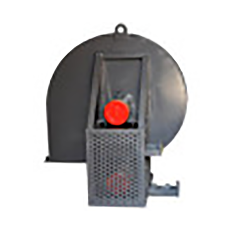
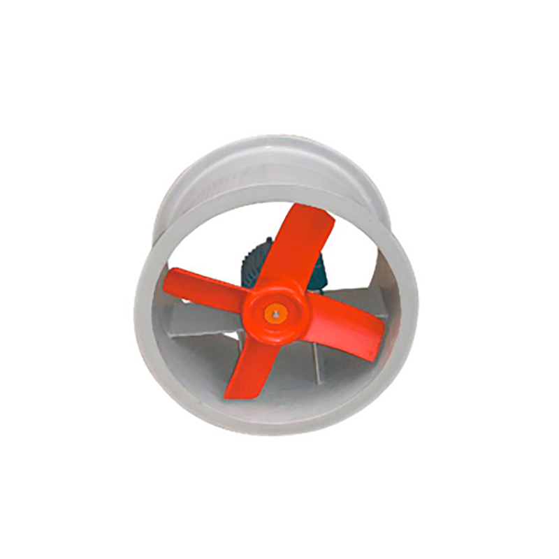
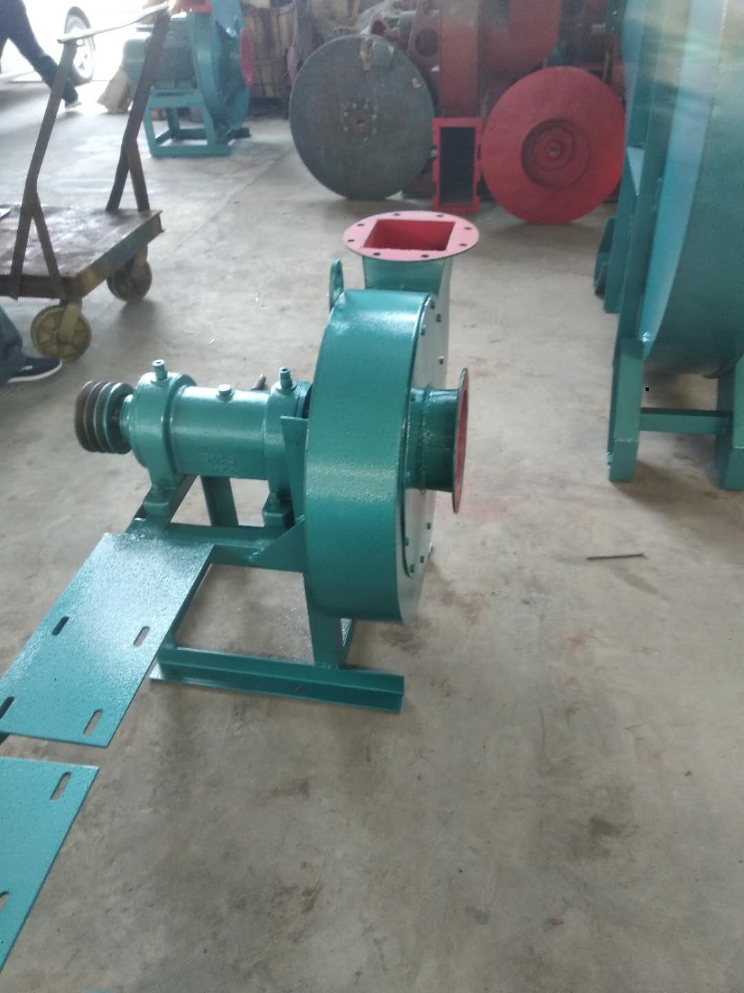
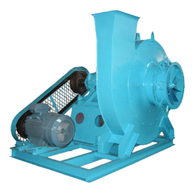
customized Industrial dust collector The fan is a kind of driven fluid machinery, which relies on the input mechanical energy to increase the gas pressure and discharge gas. Fan is the abbreviation of Chinese custom for gas compression and gas transmission machinery. Generally speaking, fans include fans, blowers, and wind turbines. Southwest Guizhou Industrial dust collector manufactor Fans are widely used for ventilation, dust discharge and cooling of factories, mines, tunnels, cooling towers, vehicles, ships and buildings, as well as ventilation and induced draft of boilers and industrial furnaces; Cooling and ventilation in air conditioning equipment and household appliances; Drying and delivery of grain, wind source of wind tunnel and inflation and propulsion of hovercraft
customized Industrial dust collector The reasons for failure caused by unstable operation are: improper temperature control of insulator box; The gas distributor grid is blocked, and the sediment electrode has too thick scale; Improper adjustment of water film; The oxygen content in the system exceeds the standard. ① Insufficient steam pressure and blocked steam pipeline may cause low temperature of insulator box. In the long run, the insulator surface temperature is low, and tar and dust particles accumulate, causing electric field short circuit. If the temperature of insulator box rises too fast, or the temperature changes violently during operation, the insulator will be cracked. ② Industrial dust collector manufactor If intermittent flushing cannot be carried out as required during operation, the tar accumulated on the sediment pipe wall is difficult to be thoroughly cleaned, which, accumulated over time, not only causes excessive resistance to equipment operation, but also leads to damage to the electric field. ③ During maintenance, the water film is not adjusted as required, the water film is uneven or not thick enough, and after putting into operation, the phenomenon described in fault (4) will occur. The above situation also occurs when the water film is damaged during operation. ④ The reason for the explosion of the electrostatic precipitator is that the oxygen content in the gas exceeds the standard, the mixed explosive gas is formed in the equipment and reaches the explosion limit, and the explosion occurs when encountering electric sparks.


