2. The influence of the total pressure deviation Δ H of the fan itself was not considered during selection. When the actual total pressure of the fan was positive deviation, the flow increased; When the actual total pressure of the fan is negative deviation, the flow decreases. See (a) below. The relationship between the deviation of the pipe network characteristic curve and the total pressure and the flow can be eliminated by one of the following methods when the fan starts to officially operate after new installation, or when the flow is too large or too small during use. 1. Use the opening and closing of throttling device to adjust the flow. 2. Increase or decrease the flow by increasing or decreasing the fan speed. 3. Use a new fan with higher or lower pressure to increase or decrease the flow. 4. Change the pipe network to reduce the resistance coefficient of the pipe network to increase the flow. It must be pointed out that throttling devices are generally used to regulate the flow. However, when the actual flow is much larger than the required flow, this method wastes too much power and is very uneconomical. If conditions permit, the fan speed is usually reduced or the fan with lower pressure is replaced. When the throttling device is fully open, the flow is still too small. At this time, the throttling device has lost its function, so try to reduce the resistance coefficient of the pipe network to increase the flow, or increase the fan speed and replace the fan with higher pressure. However, the speed of the fans directly connected to the motor and the coupling cannot be changed generally. Only the fan driven by the pulley can increase or decrease the speed by changing the diameter of the pulley, but the speed of the fan cannot exceed the speed max in the performance and selection table.
major Wet electrostatic precipitator The wet electrostatic precipitator mainly has two structural forms. One is to use corrosion-resistant conductive materials (which can be non-metallic materials with excellent conductivity or metal materials with corrosion-resistant characteristics) as the dust collector, and the other is to use non-conductive non-metallic materials as the dust collector by forming a conductive water film through water spray or overflow. Wet electrostatic precipitators can also be divided into cross flow type (horizontal) and vertical flow type (vertical) according to the flow direction of waste gas. The cross flow type is mostly plate structure, Yingtan Wet electrostatic precipitator The gas flows in and out in the horizontal direction, and the structure is similar to the dry electrostatic precipitator; The vertical flow type is mostly tubular structure, and the gas flow direction is vertical. Generally speaking, the efficiency of vertical flow wet electrostatic precipitator is twice as high as that of cross flow wet electrostatic precipitator under the condition of the same ventilation cross-sectional area. The dust deposited on the electrode plate can be washed down by water. Wet dust removal can avoid the re flying of captured dust and achieve high dust removal efficiency. Since there is no rapping device, the operation is also more reliable. The device that forms conductive film on the surface of the dust collector by means of water spray or overflow water has problems of corrosion, sludge and sewage treatment. It is only used when the dust concentration of the gas is low and the dust removal efficiency is required to be high; The wet electrostatic precipitator using corrosion-resistant conductive materials as dust collector does not need long-term water spraying or overflow water, Wet electrostatic precipitator manufactor Regular flushing is only carried out according to the operating conditions of the system, and only a small amount of water is consumed. This part of water can be recycled, and the dust collection system is basically free of secondary pollution.

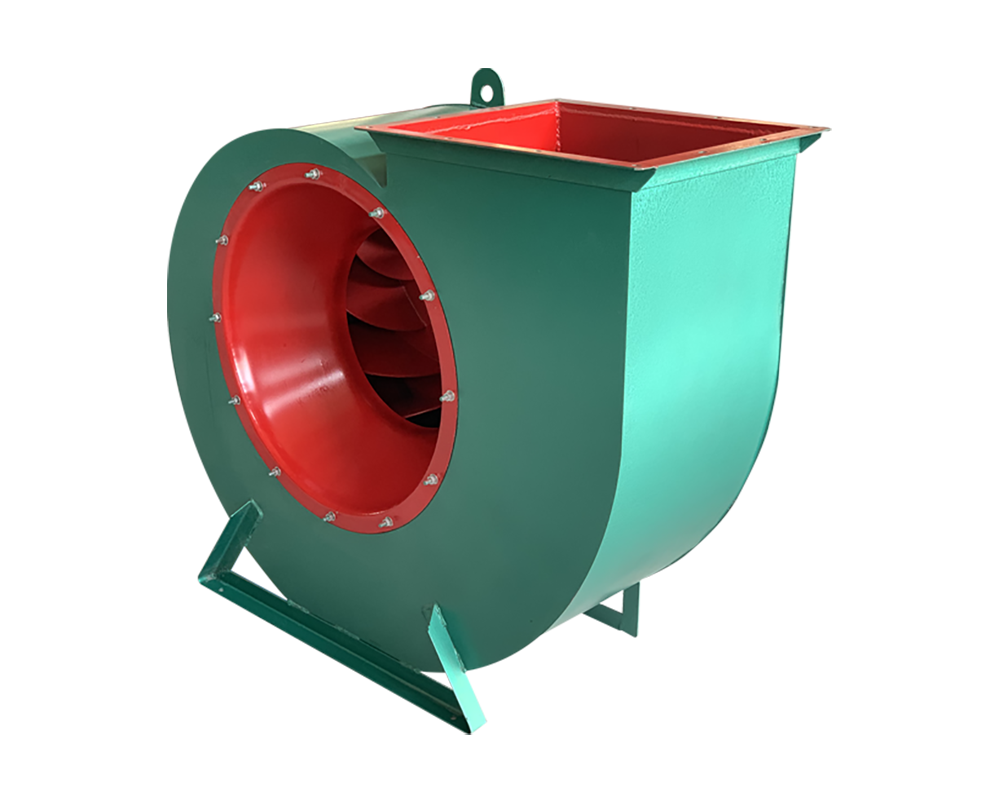
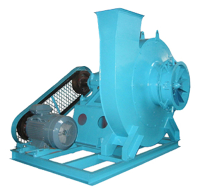
Fans can be classified into several types according to the materials used, such as iron shell fans (ordinary fans), glass fiber reinforced plastic fans, plastic fans, aluminum fans, stainless steel fans, etc. Wet electrostatic precipitator manufactor In the direction of gas flow. Fans can be classified into centrifugal, axial, diagonal (mixed flow) and cross flow fans according to the direction of gas flow. (1) Centrifugal fan. The airflow enters the impeller of the fan axially and flows mainly along the radial direction. This type of fan is made according to the principle of centrifugal action, and its products include centrifugal fan, centrifugal blower and centrifugal compressor. (2) Axial flow fan. The airflow enters the impeller of the fan axially and flows approximately along the axis on the cylindrical surface. Such fans include axial fans, axial blowers and axial compressors. (3) Rotary fan. Yingtan major Wet electrostatic precipitator Use the rotor rotation to change the air chamber volume to work. Common varieties include Roots blower and rotary compressor.
The wet electrostatic precipitator has been recognized by users due to many advantages in the process of application. It can remove dust and purify waste gas. It is an environmental protection equipment that can be used in a wide range of situations. What steps can we take when using this environmental protection equipment? today Wet electrostatic precipitator manufactor Let's take a detailed look. 1. First, close the power switch of the wet electrostatic precipitator. When the power indicator is on, the local remote switch will be switched to the local position; 2. Press the fan start button, and then observe whether the fan of the wet electrostatic precipitator rotates correctly. After the fan rotates normally, normal dedusting operation can be started; 3、 major Wet electrostatic precipitator After a period of time, if you need to clear and discharge the ash, you can press the ash cleaning button on the wet electrostatic precipitator; 4. Turn over the pulse valve to clear the ash, and the screw machine and ash discharge valve will also work together. The above is the whole content of the application process of the wet electrostatic precipitator. What we need to remind us here is that the equipment can be started only after the position is adjusted before it is used. During the dust removal process of the equipment, the humidification function can be started to keep the ground wet, so that the wet electrostatic precipitator can have a better application effect.
Selection and application of fan performance (I) Description of fan performance: 1. № 10, 12, 16, 20 are converted according to dimensionless performance of № 10 model. 2. № 5, 6, 8 are converted according to dimensionless performance of № 5 model. 3. № 5 and below shall be determined according to the performance of the measured prototype. Note: According to the dimensionless performance curve conversion formula, total pressure H=ρ u2 H (Pa) flow Q=900 π D22 uQ (m3/h) shaft power N=N × D22u3 ρ/4000 (kw), where D2 - impeller outer diameter (m) u - impeller outer edge linear speed (m/s) ρ - gas density (Kg/m3), the required power rate shall be based on shaft power plus mechanical loss and motor reserve. 4. The solid line is № 5 model, and the dotted line is № 10 model. The performance of the fan is expressed by the flow, total pressure, main shaft speed, shaft power, efficiency and other parameters of the fan, and there are certain relationships between the parameters, which are listed in the following table. The relationship of fan performance parameters changes density ρ, speed n changes speed n, atmospheric pressure P, gas temperature t Q1/Q2=n1/n2 H1/H2=(n1/n2) 2 ρ 1/ρ 2 N1/N2=(n1/n2) 3 ρ 1/ρ 2 η 1=η 2 Q1/Q2=n1/n2 H1/H2=(n1/n2) 2 (P1/P2) (273+t2/273+t1) N1/N2=(n1/n2) 3 (P1/P2) (273+t2/273+t1) η 1=η 2 Note: 1. In the middle, Q represents flow (m3/h), H represents total pressure (Pa), N Represents shaft power (kw), η represents total pressure efficiency, ρ represents density (kg/m3), t represents temperature (℃), n represents speed (r/min), and P represents atmospheric pressure (Pa). 2. The footnote symbol 2 indicates the known performance and related parameters, and the footnote symbol 1 indicates the required performance and related parameters. (
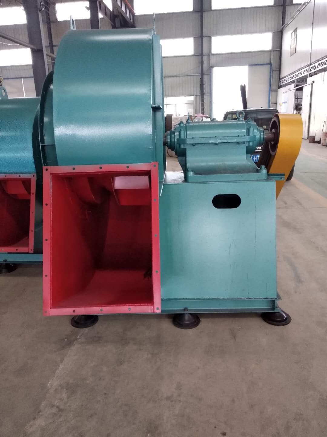
3. When installing Type C and Type B, ensure that the two pulley positions are on the same plane, and the flatness tolerance is 0.5mm. 4. When installing Type D, use a dial indicator and feeler gauge to measure the coaxiality of the fan spindle and motor spindle and the parallelism of both ends of the coupling. The coaxiality tolerance of two shafts is 0.2mm, the parallelism tolerance of both ends of the coupling is 0.2mm, and the spacing between two planes of the coupling is 5 to 8mm. 5. After the fan is installed, move the rotor with hand or lever to check whether it is too tight or collided. The test run can be carried out without overtightening or collision. 6. After the motor is installed, the belt pulley or coupling guard shall be installed. If the air inlet is not connected to the air inlet pipe, the guard net or other safety devices (provided by the user) shall also be provided. 7. Other parts shall be installed according to the corresponding positions in the drawing. 8. Add N46 (ISO VG46, 30) in summer and N32 (ISO VG32, 20) in winter. The oil level should be at 1/2 of the oil window.


