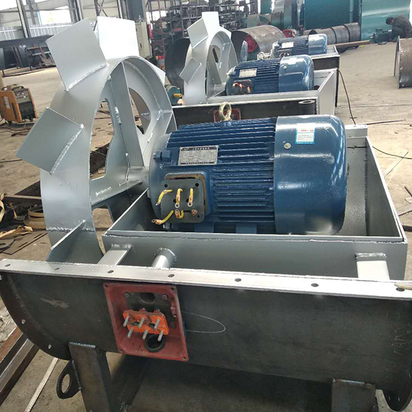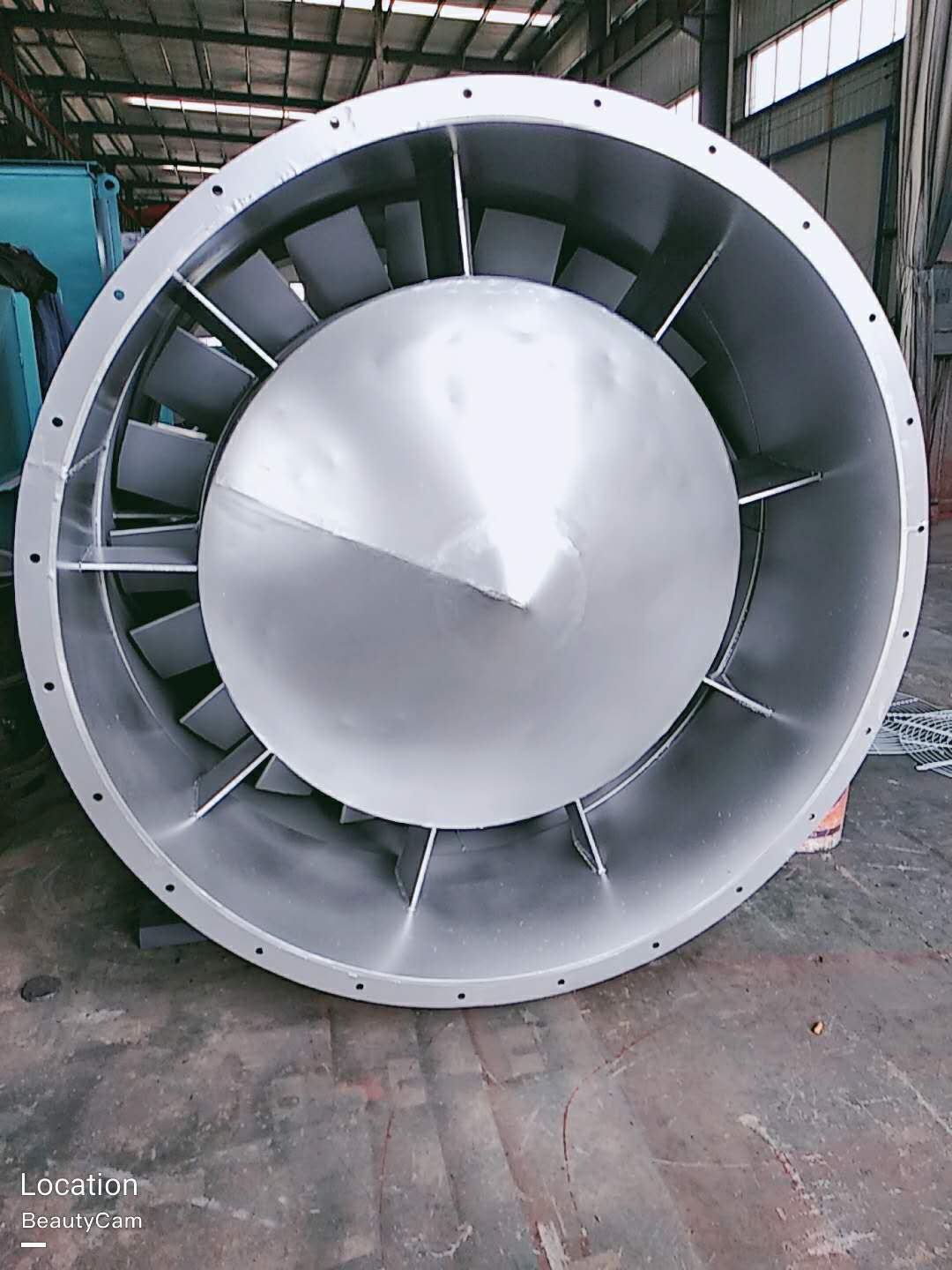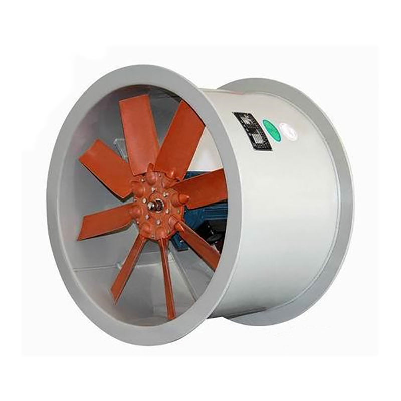
Yichang Centrifugal fan Classified by layers. There are many classification methods for fans, which can be roughly classified according to the following levels: (1) According to the level of pressure generated, they can be divided into: volumetric: reciprocating and rotary; Turbine type: centrifugal, axial flow, mixed flow and cross flow, jet type. Fan generally refers to turbine type, namely centrifugal, axial, mixed flow, cross flow and other forms. Its main characteristics are: centrifugal fan: higher pressure, but smaller air volume. Axial flow fan: higher air volume, but lower pressure. Mixed flow fan: the air volume and pressure are between centrifugal fan and axial fan. Horizontal fan: with high dynamic pressure, it can obtain flat airflow. (2) large Centrifugal fan According to the different materials used, it can be divided into:; Iron shell fan (ordinary fan), glass fiber reinforced plastic fan, plastic fan, aluminum fan, stainless steel fan, etc. (3) According to the direction of gas flow, it can be divided into centrifugal type, axial flow type, diagonal flow type (mixed flow type) and cross flow type. (4) According to the flow direction of the airflow entering the impeller, it can be divided into axial flow fan, centrifugal fan and diagonal flow (mixed flow) fan. (5) Centrifugal fan manufactor It can be divided into: press in local fans and flame-proof motors placed outside or inside the flow channel, and flame-proof motors placed inside the explosion-proof sealing chamber of the extraction type local fans. (6) According to the form of pressurization, it can also be divided into single-stage, two-stage or multi-stage pressurization fans

(2) Precautions for normal operation of fan 1. If the flow is found to be too large, which does not meet the operating requirements, or less flow is required in a short time, the throttling device can be used to adjust to meet the operating requirements. 2. The sensitivity of thermometer and oil pointer shall be checked regularly. 3. In case of any abnormal phenomenon during the start-up, shutdown or operation of the fan, it shall be checked in time. 4. For minor faults found in the inspection, find out the causes in time and try to eliminate or deal with them. If minor faults cannot be eliminated or major faults are found, repair them immediately. 5. In addition to replacing the lubricating oil during each maintenance, the lubricating oil shall also be replaced regularly. Observe the oil level at ordinary times and replenish lubricating oil in time.

Preparations for fan installation. large Centrifugal fan Before unpacking the fan, check whether the package is intact, whether the nameplate parameters of the fan meet the requirements, and whether all accompanying accessories are complete. Carefully check whether the fan is deformed or damaged during transportation, whether the fasteners are loose or fall off, and whether the impeller is scratched, and check all parts of the fan. Yichang Centrifugal fan manufactor If any abnormality is found, it shall be repaired before use. Use a 500V megger to measure the insulation resistance between the fan housing and the motor winding. The value should be greater than 0.5 megohm. Otherwise, the motor winding should be dried. The temperature during drying should not exceed 120 ℃. Prepare various materials, tools and sites required for fan installation.

3. When installing Type C and Type B, ensure that the two pulley positions are on the same plane, and the flatness tolerance is 0.5mm. 4. When installing Type D, use a dial indicator and feeler gauge to measure the coaxiality of the fan spindle and motor spindle and the parallelism of both ends of the coupling. The coaxiality tolerance of two shafts is 0.2mm, the parallelism tolerance of both ends of the coupling is 0.2mm, and the spacing between two planes of the coupling is 5 to 8mm. 5. After the fan is installed, move the rotor with hand or lever to check whether it is too tight or collided. The test run can be carried out without overtightening or collision. 6. After the motor is installed, the belt pulley or coupling guard shall be installed. If the air inlet is not connected to the air inlet pipe, the guard net or other safety devices (provided by the user) shall also be provided. 7. Other parts shall be installed according to the corresponding positions in the drawing. 8. Add N46 (ISO VG46, 30) in summer and N32 (ISO VG32, 20) in winter. The oil level should be at 1/2 of the oil window.


