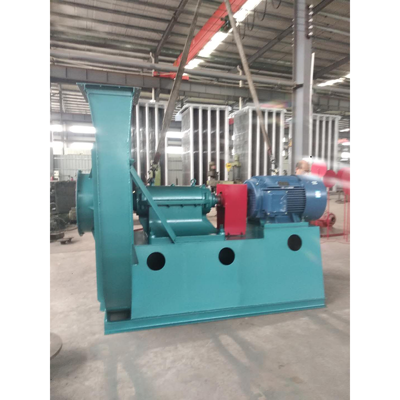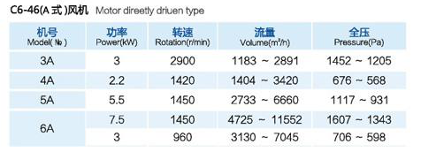
The selection of fans Product performance and fan performance listed in the selection table are based on the performance of delivering air under standard conditions. Therefore, when the use condition is non-standard, the H4-72-12 centrifugal fan must convert the use performance into the performance under standard conditions according to the relationship in the table above, and then select according to the performance and selection table. (3) Treatment of excessive or insufficient flow During use, excessive or insufficient flow often occurs. There are many reasons for this phenomenon. If the flow is high and low during use, it is mainly because the resistance in the pipe network is high and low, or the fan works in a non working area. If it is gradually reduced after a long time during use, it is mainly due to pipe network blockage. After the fan is newly installed, the flow is too large or insufficient during the formal operation. The main reasons for this phenomenon are as follows: 1. The actual value of pipe network resistance is too different from the calculated value. In the general pipe network characteristic equation, H=KQ2, if the actual value K of K-resistance coefficient is less than the calculated value K, the flow will increase; If the actual value K is greater than the calculated value K, the flow decreases. See (b) below.

Main working principles of wet electrostatic precipitator: large Wet dedusting equipment Spray the water mist to the discharge electrode and corona area, the water mist will split and further atomize after being charged in the powerful corona field formed by the barbed electrode, and the collision interception, adsorption and coagulation of electric field force and charged water mist will jointly trap the dust particles, and finally the dust particles will reach the dust collector under the drive of electric field force and be trapped. The water forms a continuous water film on the dust collecting electrode, and the captured dust is washed into the ash hopper and discharged with water. Operating principle of wet electrostatic precipitator. The dedusting process of electrostatic precipitator can be divided into four stages: gas ionization; The dust is charged with ions; Charged dust moves towards the electrode; Remove the dust on the electrode. Only the objects removed by wet electrostatic precipitation are dust and droplets, but their working principles are different due to the differences in physical characteristics between droplets and dust. In principle, Wuzhou Wet dedusting equipment First of all, the existence of water droplets has an impact on the electrode discharge. To form emitting ions, free electrons in the metal electrode must obtain enough energy to overcome the ionization energy and cross the surface barrier to become emitting electrons. It is an effective measure to reduce the surface barrier by bringing water on the electrode surface. After the metal surface is covered with water, the original "metal air" interface is divided into "metal water" interface and "water air" interface. The potential barrier of the latter two interfaces is much lower than that of the former interface. In this way, after the metal surface is filled with water, the original high barrier will be divided into two low barriers, which will greatly weaken the blocking effect of the surface barrier on free electrons and make electrons easy to launch. In addition, Wet dedusting equipment company Under the action of electric field, various impurity ions in water can easily cross the surface barrier and become emission ions. All of these have changed the electrode discharge effect, enabling corona discharge under low voltage. Secondly, due to the existence of water droplets, the resistance of water is relatively small. When water droplets combine with dust, the specific resistance of dust with high specific electricity decreases, so the working state of wet electrostatic precipitator will be more stable; In addition, since the wet electrostatic precipitator is washed by water flow and has no rapping device, it will not produce secondary dust.

3. When installing Type C and Type B, ensure that the two pulley positions are on the same plane, and the flatness tolerance is 0.5mm. 4. When installing Type D, use a dial indicator and feeler gauge to measure the coaxiality of the fan spindle and motor spindle and the parallelism of both ends of the coupling. The coaxiality tolerance of two shafts is 0.2mm, the parallelism tolerance of both ends of the coupling is 0.2mm, and the spacing between two planes of the coupling is 5 to 8mm. 5. After the fan is installed, move the rotor with hand or lever to check whether it is too tight or collided. The test run can be carried out without overtightening or collision. 6. After the motor is installed, the belt pulley or coupling guard shall be installed. If the air inlet is not connected to the air inlet pipe, the guard net or other safety devices (provided by the user) shall also be provided. 7. Other parts shall be installed according to the corresponding positions in the drawing. 8. Add N46 (ISO VG46, 30) in summer and N32 (ISO VG32, 20) in winter. The oil level should be at 1/2 of the oil window.

In order to avoid man-made faults and accidents caused by improper maintenance, prevent the occurrence of natural faults and accidents of fans and motors in all aspects, so as to give full play to the efficiency of equipment and extend the service life of equipment, therefore, the maintenance of fans must be strengthened. (1) Working system of fan maintenance The fan maintenance personnel must pay attention to the following points: 1. The fan can only be operated when the fan equipment is completely normal. 2. If the fan equipment starts after maintenance, pay attention to whether all parts of the fan are normal. 3. Regularly clean the dust, dirt, water and other impurities inside the fan and gas transmission pipeline, and check whether the impeller is worn and rusted, if any, repair and replace it in time. 4. Regularly replace the lubricating oil (recommended 3-6 months). It is recommended to add N46 (ISO VG46, 30) in summer and N32 (ISO VG32, 20) in winter. The oil level should be at 1/2 of the oil window. 5. Check the coupling and belt pulley regularly (3-6 months is recommended), and repair and replace them immediately if parts are worn or rusted. 6. The equipment shall not be repaired during operation.


