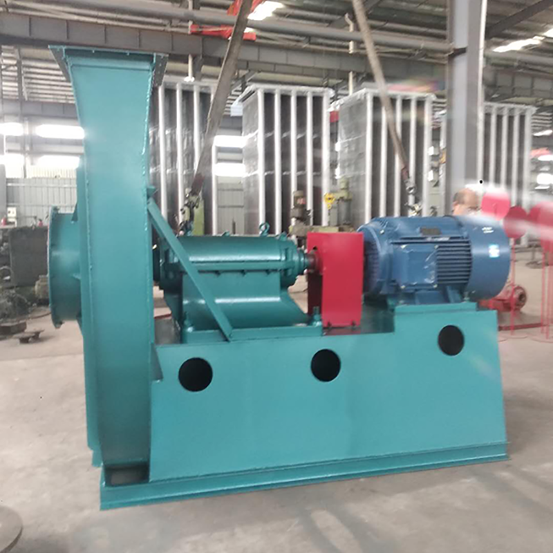
3. When installing Type C and Type B, ensure that the two pulley positions are on the same plane, and the flatness tolerance is 0.5mm. 4. When installing Type D, use a dial indicator and feeler gauge to measure the coaxiality of the fan spindle and motor spindle and the parallelism of both ends of the coupling. The coaxiality tolerance of two shafts is 0.2mm, the parallelism tolerance of both ends of the coupling is 0.2mm, and the spacing between two planes of the coupling is 5 to 8mm. 5. After the fan is installed, move the rotor with hand or lever to check whether it is too tight or collided. The test run can be carried out without overtightening or collision. 6. After the motor is installed, the belt pulley or coupling guard shall be installed. If the air inlet is not connected to the air inlet pipe, the guard net or other safety devices (provided by the user) shall also be provided. 7. Other parts shall be installed according to the corresponding positions in the drawing. 8. Add N46 (ISO VG46, 30) in summer and N32 (ISO VG32, 20) in winter. The oil level should be at 1/2 of the oil window.

Before installation, first prepare the materials and tools for installation, and check the parts of the fan, especially the impeller, main shaft, bearing and other parts. If any damage is found, repair it, and then clean the inside of the bearing box with kerosene. In the process of installation, the following points must be paid attention to: 1. In order to prevent rust and reduce the difficulty of disassembly, some grease or machine oil should be coated on some joint surfaces. 2. When installing the bolts on the joint surface, if there are positioning pins, install the pins and tighten them before tightening the bolts. 3. Check that there should be no tools and sundries falling or left in the casing and other casings. Installed and used by CHANG factory bridge QIAO ISO9001 quality management system certification enterprise of Beijing No. 2 Blower Works 1. When installing the fan, the inlet and outlet must be provided with soft connection, and the weight of the gas transmission pipeline should not be added to the casing. Correct the gap size between the air inlet and the impeller according to the drawing, and keep the shaft in a horizontal position. 2. When installing the soft connection of the air inlet, the bolts of the air inlet itself can be directly used for connection. At this time, the air inlet is fixed by three countersunk screws.

9. Since the flow, total pressure, main shaft speed and shaft power of the fan have a fixed relationship, the main shaft speed should not be changed when the motor capacity does not change. If the main shaft speed increases, the motor may be burned due to overload. The motor power used by the fan refers to the power not required when the air inlet and outlet are fully open in terms of mechanical losses and due reserves under a specific mine. If the outlet or inlet of the fan is not connected to the pipeline or is idle without external resistance, the motor may also be burned out. For safety, a valve shall be added to the outlet or inlet pipeline of the fan, and it shall be closed when starting the motor. After turning, the valve shall be slowly opened until the specified working condition is reached, and attention shall be paid to whether the current of the motor exceeds the specified value. High power motors must be started in proper ways, such as voltage reduction, frequency conversion, etc.

Selection and application of fan performance (I) Description of fan performance: 1. № 10, 12, 16, 20 are converted according to dimensionless performance of № 10 model. 2. № 5, 6, 8 are converted according to dimensionless performance of № 5 model. 3. № 5 and below shall be determined according to the performance of the measured prototype. Note: According to the dimensionless performance curve conversion formula, total pressure H=ρ u2 H (Pa) flow Q=900 π D22 uQ (m3/h) shaft power N=N × D22u3 ρ/4000 (kw), where D2 - impeller outer diameter (m) u - impeller outer edge linear speed (m/s) ρ - gas density (Kg/m3), the required power rate shall be based on shaft power plus mechanical loss and motor reserve. 4. The solid line is № 5 model, and the dotted line is № 10 model. The performance of the fan is expressed by the flow, total pressure, main shaft speed, shaft power, efficiency and other parameters of the fan, and there are certain relationships between the parameters, which are listed in the following table. The relationship of fan performance parameters changes density ρ, speed n changes speed n, atmospheric pressure P, gas temperature t Q1/Q2=n1/n2 H1/H2=(n1/n2) 2 ρ 1/ρ 2 N1/N2=(n1/n2) 3 ρ 1/ρ 2 η 1=η 2 Q1/Q2=n1/n2 H1/H2=(n1/n2) 2 (P1/P2) (273+t2/273+t1) N1/N2=(n1/n2) 3 (P1/P2) (273+t2/273+t1) η 1=η 2 Note: 1. In the middle, Q represents flow (m3/h), H represents total pressure (Pa), N represents shaft power (kw), η represents full pressure efficiency, ρ represents density (kg/m3), t represents temperature (℃), n represents speed (r/min), and P represents atmospheric pressure (Pa). 2. The footnote symbol 2 indicates the known performance and related parameters, and the footnote symbol 1 indicates the required performance and related parameters. (


