The key points of factors to be considered in the technical approach to the transformation of wet electrostatic precipitators: the wet electrostatic precipitators built before the mid-1970s could not meet the requirements of the new emission standards because of the low requirements for boiler smoke and dust emissions, the small selection of equipment capacity, the outdated structure of electrostatic precipitators, aging of dust removal equipment, low dust removal efficiency and other reasons, These electrostatic precipitators have a problem of transformation to further improve efficiency. customized Wet electrostatic precipitator company The improvement measures for the original equipment should be considered from both technical and economic aspects, and the following technical approaches are generally adopted: 1. Discover the potential of electrostatic precipitator equipment. For example, adjust the rapping cycle and rapping force of the electrode to improve the corona power and reduce the re flying of dust; Improve the uneven distribution of flue gas velocity and readjust the technical parameters of the airflow distribution device; Adjust the control mode or power supply mode of the power supply equipment. 2、 customized Wet electrostatic precipitator Combination with other dedusting equipment. That is, a primary precipitator is added before or after the electrostatic precipitator. 3. Increase the capacity (or dust collection area) of the electrostatic precipitator. That is, add an electric field, or increase or widen the electric field of the electrostatic precipitator.

The selection basis of wet dust collector is as follows. ① customized Wet electrostatic precipitator Dust removal efficiency. Whether the efficiency of wet dust collector is high or not is one of the most important performance indicators to be selected. Under certain conditions, the gas flow, specific dust pollutants, and the gas state have a direct impact on the collection efficiency. ② Operational flexibility. Wet electrostatic precipitator company Any operating equipment shall consider its negative flow, and the impact on the capture efficiency when the air flow exceeds or is lower than the design value; Similarly, it is necessary to know how to operate when the dust concentration is unstable or continuously higher than the design value. ③ Hydrophobicity. The purification efficiency of wet dust collector for hydrophobic dust is not high, and generally it is not suitable for the operation at the design value. ④ Adhesion. Wet dust collector can purify cohesive dust, but flushing and cleaning shall be considered to prevent blockage, ⑤ corrosiveness. Anticorrosion measures shall be considered when purifying corrosive gas, ⑥ water consumption. How much water is consumed by the dust remover, sewage treatment and anti freezing measures for water in winter. ⑦ Mud treatment. Mud treatment is an inevitable problem for wet dust collectors, and efforts should be made to reduce the harm of pollution. ⑧ Operation and maintenance. Luzhou Wet electrostatic precipitator company Generally, moving or rotating parts inside the dust remover shall be avoided, and it shall be noted that if the gas passes through the channel section too small, it will cause blockage.

Dust leakage may occur when the wet electrostatic precipitator is used at ordinary times, so that the precipitator can not achieve the expected use effect when it is used Wet electrostatic precipitator company Let's specifically analyze the causes of dust leakage. 1. The dust remover is mainly assembled from the clean air chamber and the hopper. In this part, screws are used at the connection position between the upper box and the hopper. If the sealing strip used in this place is unqualified, dust will leak out. In addition to affecting the normal use of the equipment, the poor performance of the dust remover in use will have a great impact on the environment of the whole workshop and the surrounding environment. Even some wet electrostatic precipitators have a lot of materials with recycling value in the recycled dust. two Luzhou customized Wet electrostatic precipitator Improper filtering wind speed used in dedusting may also lead to dust leakage, because the dust will be adsorbed on the filter bag when the temperature is too high, so the resistance of dedusting equipment will increase when it is used, leading to leakage. 3. The dedusting bag is also a device that plays a major role in the operation and use of the equipment. If the density of the bag itself is relatively small, it may cause dust leakage to each other. Therefore, when selecting the bag, it is also necessary to select the one with better quality for use, and it is also necessary to do a good job of maintenance when using it again.

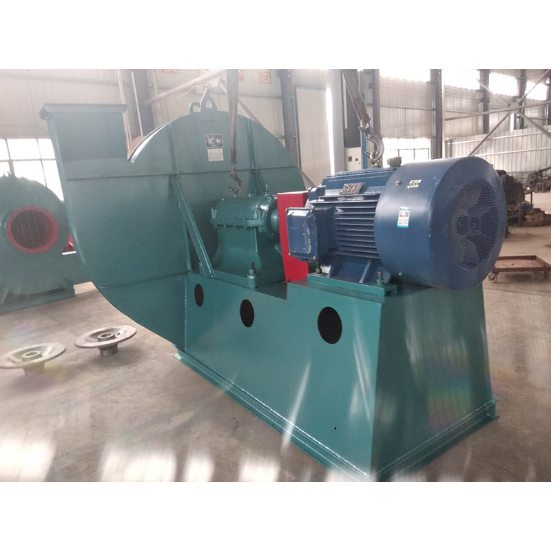
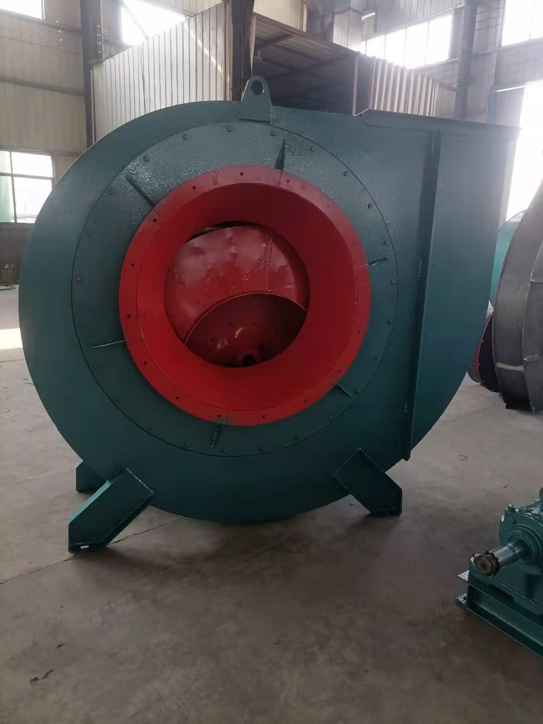
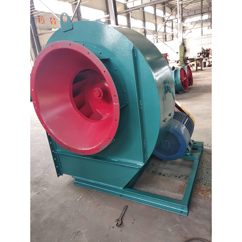
Wet electrostatic precipitator company The work starts before the fan is used. one Luzhou Wet electrostatic precipitator company Carefully read the fan operation instructions and product samples, and be familiar with and understand the fan specifications, forms, impeller rotation direction and air flow in and out direction; Check whether all parts of the fan are in good condition again, or they can be installed and used only after being repaired. 2. The fan must be installed with safety devices to prevent accidents, and installed and wired by professionals familiar with relevant safety requirements. 3. The air duct connecting the inlet and outlet of the fan has separate support, and it is not allowed to add the overlapping weight of the duct to the components of the fan; When installing the fan, pay attention to the horizontal position of the fan, and adjust the connection between the joint surface of the fan and the foundation and the air outlet pipe to make it coincide naturally. Forced connection is not allowed. four customized Wet electrostatic precipitator After the fan is installed, move the impeller by hand or lever to check whether it is too tight or rubbed, and whether there is any object that hinders the rotation. The test run can be carried out only when there is no abnormal phenomenon. The exposed part of the fan transmission device should be equipped with a protective cover (provided by the user). If the fan inlet is not connected, a protective screen or other installation device (provided by the user) should also be added. 5. The power distribution control box of the fan must match the corresponding fan (power, voltage, pneumatic mode, control mode, etc.). 6. The fan wiring should be made by a professional electrician, and the wiring must be correct and reliable. Especially, the wiring number at the electric control box should be consistent with the number on the fan terminal. The fan shell should be reliably grounded. The grounding must be reliable, and zero connection cannot be used instead of grounding. 7. After all fans are installed, check whether there are any left tool box sundries inside the fan

Selection and application of fan performance (I) Description of fan performance: 1. № 10, 12, 16, 20 are converted according to dimensionless performance of № 10 model. 2. № 5, 6, 8 are converted according to dimensionless performance of № 5 model. 3. № 5 and below shall be determined according to the performance of the measured prototype. Note: According to the dimensionless performance curve conversion formula, total pressure H=ρ u2 H (Pa) flow Q=900 π D22 uQ (m3/h) shaft power N=N × D22u3 ρ/4000 (kw), where D2 - impeller outer diameter (m) u - impeller outer edge linear speed (m/s) ρ - gas density (Kg/m3), the required power rate shall be based on shaft power plus mechanical loss and motor reserve. 4. The solid line is № 5 model, and the dotted line is № 10 model. The performance of the fan is expressed by the flow, total pressure, main shaft speed, shaft power, efficiency and other parameters of the fan, and there are certain relationships between the parameters, which are listed in the following table. The relationship of fan performance parameters changes density ρ, speed n changes speed n, atmospheric pressure P, gas temperature t Q1/Q2=n1/n2 H1/H2=(n1/n2) 2 ρ 1/ρ 2 N1/N2=(n1/n2) 3 ρ 1/ρ 2 η 1=η 2 Q1/Q2=n1/n2 H1/H2=(n1/n2) 2 (P1/P2) (273+t2/273+t1) N1/N2=(n1/n2) 3 (P1/P2) (273+t2/273+t1) η 1=η 2 Note: 1. In the middle, Q represents flow (m3/h), H represents total pressure (Pa), N represents shaft power (kw), η represents full pressure efficiency, ρ represents density (kg/m3), t represents temperature (℃), n represents speed (r/min), and P represents atmospheric pressure (Pa). 2. The footnote symbol 2 indicates the known performance and related parameters, and the footnote symbol 1 indicates the required performance and related parameters. (


