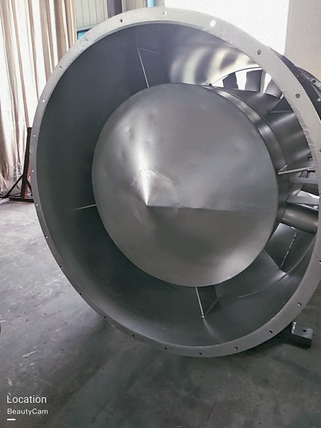
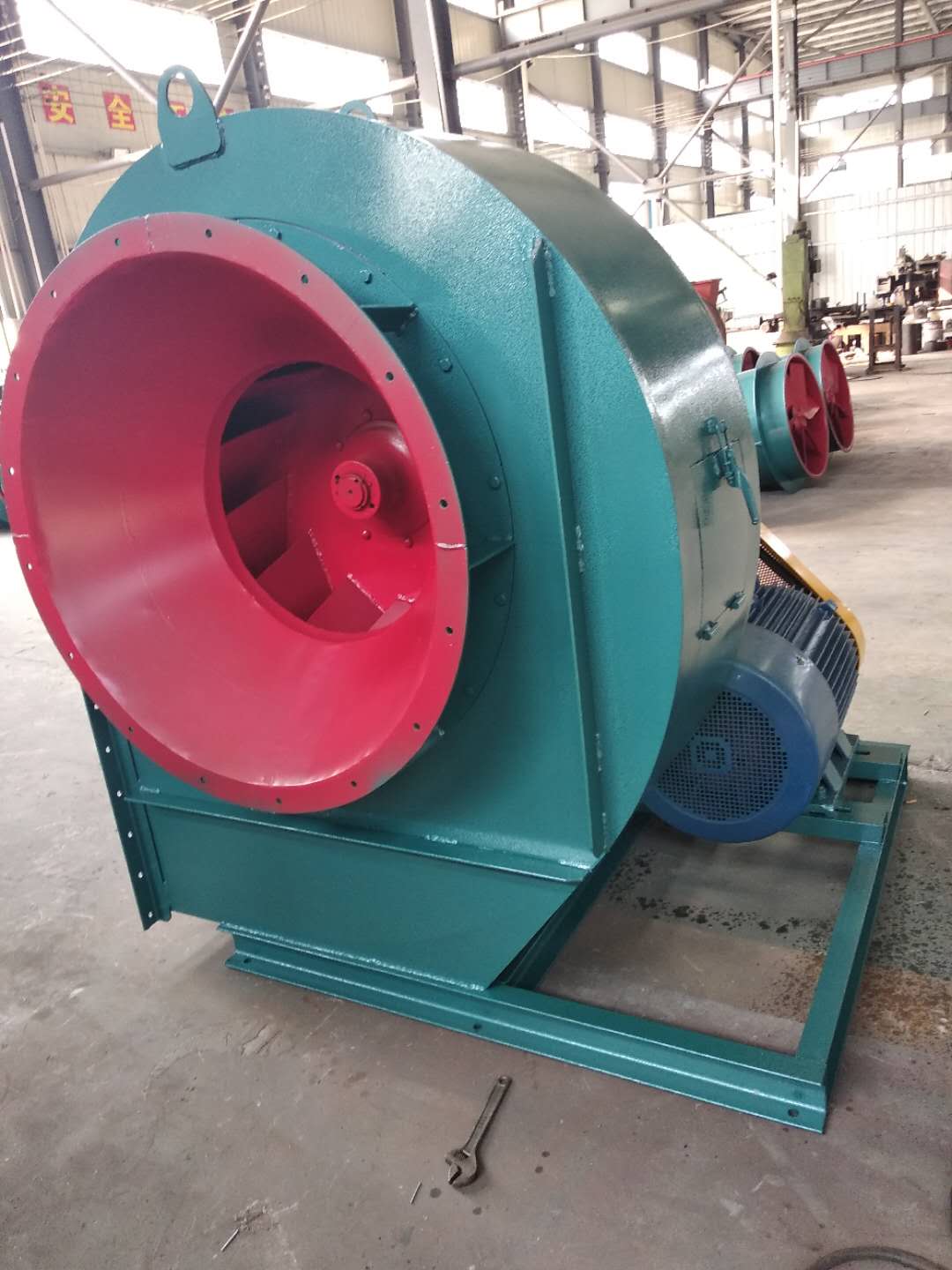
(3) The main faults and causes of the fan may occur during the operation of the fan. For the faults generated, the causes must be quickly identified and solved in time to prevent accidents. Faults in the Operation of 4-72-12 Centrifugal Fan and the Causes Table Fault Name Causes Severe Vibration of Bearing Box 1. The fan shaft is different from the motor shaft, and the coupling is installed askew. 2. The casing or air inlet rubs with the impeller. 3. The foundation stiffness is not enough or firm. 4. Impeller rivet is loose or wheel disc is deformed. 5. The impeller shaft disk and shaft are loose, and the coupling bolt is movable. 6. The connection between casing and bracket, bearing box and bracket, bearing box and seat is loose. 7. The air inlet and outlet pipes of the fan are poorly installed, causing vibration. 8. The rotor is unbalanced. Bearing temperature rise is too high 1. The bearing box vibrates violently. 2. The lubricating grease is poor in quality, deteriorated or overfilled, or contains dust, sand, dirt and other impurities. 3. The tightening force of connecting bolts of bearing cover seat is too large or too small. 4. The shaft and rolling bearing are installed askew, and the front and rear bearings are not concentric. 5. The rolling bearing is damaged. The motor current is too high and the temperature rise is too high. 1. The throttle valve in the air inlet pipe is not closed tightly when driving. 2. The flow exceeds the specified value, or the air duct leaks. 3. The gas density conveyed by the fan is too high. 4. The input voltage of the motor is too low or the power supply is cut off individually. 5. The coupling is improperly connected, the leather ring is too tight or the gap is uneven. 6. Affected by the violent vibration of the bearing box. 7. Affected by deterioration or failure of parallel fans. When the belt slides down, the two pulleys are not in the same plane with each other. Belt runout The distance between two pulleys is too close or the belt is too long.
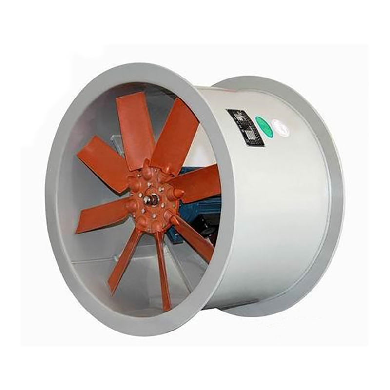
Shaanxi Dust exhaust centrifugal fan Classified by layers. There are many classification methods for fans, which can be roughly classified according to the following levels: (1) According to the level of pressure generated, they can be divided into: volumetric: reciprocating and rotary; Turbine type: centrifugal, axial flow, mixed flow and cross flow, jet type. Fan generally refers to turbine type, namely centrifugal, axial, mixed flow, cross flow and other forms. Its main characteristics are: centrifugal fan: higher pressure, but smaller air volume. Axial flow fan: higher air volume, but lower pressure. Mixed flow fan: the air volume and pressure are between centrifugal fan and axial fan. Horizontal fan: with high dynamic pressure, it can obtain flat airflow. (2) customized Dust exhaust centrifugal fan According to the different materials used, it can be divided into:; Iron shell fan (ordinary fan), glass fiber reinforced plastic fan, plastic fan, aluminum fan, stainless steel fan, etc. (3) According to the direction of gas flow, it can be divided into centrifugal type, axial flow type, diagonal flow type (mixed flow type) and cross flow type. (4) According to the flow direction of the airflow entering the impeller, it can be divided into axial flow fan, centrifugal fan and diagonal flow (mixed flow) fan. (5) Dust exhaust centrifugal fan company It can be divided into: press in local fans and flame-proof motors placed outside or inside the flow channel, and flame-proof motors placed inside the explosion-proof sealing chamber of the extraction type local fans. (6) According to the form of pressurization, it can also be divided into single-stage, two-stage or multi-stage pressurization fans
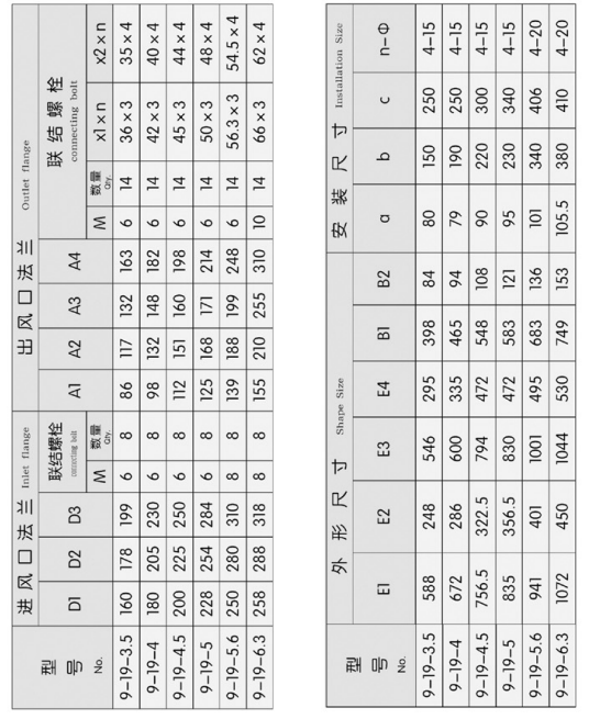
Selection and application of fan performance (I) Description of fan performance: 1. № 10, 12, 16, 20 are converted according to dimensionless performance of № 10 model. 2. № 5, 6, 8 are converted according to dimensionless performance of № 5 model. 3. № 5 and below shall be determined according to the performance of the measured prototype. Note: According to the dimensionless performance curve conversion formula, total pressure H=ρ u2 H (Pa) flow Q=900 π D22 uQ (m3/h) shaft power N=N × D22u3 ρ/4000 (kw), where D2 - impeller outer diameter (m) u - impeller outer edge linear speed (m/s) ρ - gas density (Kg/m3), the required power rate shall be based on shaft power plus mechanical loss and motor reserve. 4. The solid line is № 5 model, and the dotted line is № 10 model. The performance of the fan is expressed by the flow, total pressure, main shaft speed, shaft power, efficiency and other parameters of the fan, and there are certain relationships between the parameters, which are listed in the following table. The relationship of fan performance parameters changes density ρ, speed n changes speed n, atmospheric pressure P, gas temperature t Q1/Q2=n1/n2 H1/H2=(n1/n2) 2 ρ 1/ρ 2 N1/N2=(n1/n2) 3 ρ 1/ρ 2 η 1=η 2 Q1/Q2=n1/n2 H1/H2=(n1/n2) 2 (P1/P2) (273+t2/273+t1) N1/N2=(n1/n2) 3 (P1/P2) (273+t2/273+t1) η 1=η 2 Note: 1. In the middle, Q represents flow (m3/h), H represents total pressure (Pa), N represents shaft power (kw), η represents full pressure efficiency, ρ represents density (kg/m3), t represents temperature (℃), n represents speed (r/min), and P represents atmospheric pressure (Pa). 2. The footnote symbol 2 indicates the known performance and related parameters, and the footnote symbol 1 indicates the required performance and related parameters. (
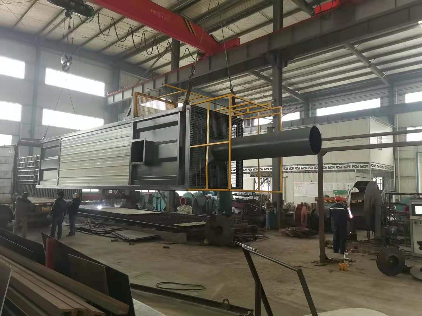
The operating principle of wet electrostatic precipitator is different from other equipment. The dusty gas enters the expanded ash hopper of the wet electrostatic precipitator for pre collection, and is evenly distributed between each filter bag through the guide plate. The dust is retained on the surface of the filter bag. In order to make the equipment resistance not exceed 1200pa, the high-pressure gas will pulse through the electromagnetic pulse valve, so that the compressed air in the air bag will be ejected from the nozzle hole (called primary air) The surrounding air (called secondary air), which is several times of the primary air, is induced through the venturi to enter the filter bag to make the filter bag expand rapidly in an instant, and shake off the dust with the reverse effect of the air flow to reach the purpose of ash removal. The microcomputer automatic control device is used to adjust the ash cleaning cycle and pulse spraying time randomly according to the dust concentration, so that the dust collector can operate within the resistance range. When changing the bag of the wet electrostatic precipitator, open the top bag changing cover and directly pull out the filter bag, which is simple and convenient to protect. Shaanxi customized Dust exhaust centrifugal fan Wet electrostatic precipitators are mostly used in bag type precipitators. Dust removal bags are installed in the gas box. Wet electrostatic precipitators are mostly external filter type. Dust is collected in the ash hopper of wet electrostatic precipitators through the injection of pulse solenoid valves. The wet electrostatic precipitator is installed in a simple structure. This device is planned as an internal filtering structure, which can change the external pressure of the wet electrostatic precipitator to the internal pressure. In this way, the shell of the wet electrostatic precipitator can be structured without external iron plate sealing, which saves costs and does not hinder the use of the wet electrostatic precipitator. The processing of wet electrostatic precipitator is particularly important. In recent years, some Dust exhaust centrifugal fan company Small manufacturers use small sewing machines as processing equipment, and use low-quality thread as raw materials during processing, which is fake, and the processing level is far behind. The wet electrostatic precipitator will open lines, cracks, and drop the bottom after a short time of operation. Although the size of the cloth bag is slightly smaller, it can also be used, but after absorbing the dust with large specific gravity, the bag will drop after a period of use.
customized Dust exhaust centrifugal fan The reasons for failure caused by unstable operation are: improper temperature control of insulator box; The gas distributor grid is blocked, and the sediment electrode has too thick scale; Improper adjustment of water film; The oxygen content in the system exceeds the standard. ① Insufficient steam pressure and blocked steam pipeline may cause low temperature of insulator box. In the long run, the insulator surface temperature is low, and tar and dust particles accumulate, causing electric field short circuit. If the temperature of insulator box rises too fast, or the temperature changes violently during operation, the insulator will be cracked. ② Dust exhaust centrifugal fan company If intermittent flushing cannot be carried out as required during operation, the tar accumulated on the sediment pipe wall is difficult to be thoroughly cleaned, which, accumulated over time, not only causes excessive resistance to equipment operation, but also leads to damage to the electric field. ③ During maintenance, the water film is not adjusted as required, the water film is uneven or not thick enough, and after putting into operation, the phenomenon described in fault (4) will occur. The above situation also occurs when the water film is damaged during operation. ④ The reason for the explosion of the electrostatic precipitator is that the oxygen content in the gas exceeds the standard, the mixed explosive gas is formed in the equipment and reaches the explosion limit, and the explosion occurs when encountering electric sparks.


