Fans can be classified into several types according to the materials used, such as iron shell fans (ordinary fans), glass fiber reinforced plastic fans, plastic fans, aluminum fans, stainless steel fans, etc. Wet dedusting equipment manufactor In the direction of gas flow. Fans can be classified into centrifugal, axial, diagonal (mixed flow) and cross flow fans according to the direction of gas flow. (1) Centrifugal fan. The airflow enters the impeller of the fan axially and flows mainly along the radial direction. This type of fan is made according to the principle of centrifugal action, and its products include centrifugal fan, centrifugal blower and centrifugal compressor. (2) Axial flow fan. The airflow enters the impeller of the fan axially and flows approximately along the axis on the cylindrical surface. Such fans include axial fans, axial blowers and axial compressors. (3) Rotary fan. Ningbo customized Wet dedusting equipment Use the rotor rotation to change the air chamber volume to work. Common varieties include Roots blower and rotary compressor.
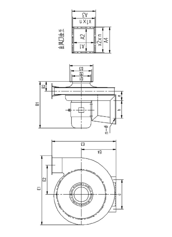
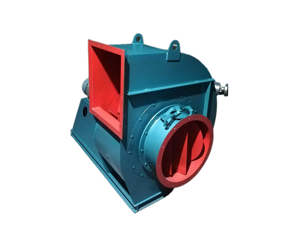
Gas compression and gas transmission machinery is a machine that converts rotating mechanical energy into gas pressure energy and kinetic energy and transports gas. The main structural components of the fan are impeller, casing, air inlet, support, motor, pulley, coupling, silencer, transmission parts (bearings), etc. customized Wet dedusting equipment The unpowered fan uses the air thermal convection caused by the natural wind force and the indoor and outdoor temperature difference to drive the turbine to rotate, thus using the centrifugal force and negative pressure effect to exhaust the indoor stale hot air. Ningbo Wet dedusting equipment manufactor The fan is related to the transmission and distribution energy consumption of the system, and is a very critical part of building energy conservation. According to the fan inspection conducted by the National Air Conditioning Equipment Quality Supervision and Inspection Center for many years, many fans have problems under rated conditions, so it is necessary to produce and manufacture fans in strict accordance with product standards. customized Wet dedusting equipment At the beginning of the fan operation, the vibration of the bearing is very small, but with the extension of the operating time, the dust in the fan will be unevenly attached to the impeller, gradually destroying the dynamic balance of the fan, making the bearing vibration gradually increase. Once the vibration reaches the maximum allowable value of 11mm/s of the fan (the maximum allowable value expressed by the amplitude value is as follows), The fan must be shut down for repair (dust accumulation shall be removed and dynamic balance shall be redone). Because it is very dangerous at this time, users must not use it forcibly. When the fan vibration is close to the dangerous value, the vibration measuring instrument will give an alarm.
In order to avoid man-made faults and accidents caused by improper maintenance, prevent the occurrence of natural faults and accidents of fans and motors in all aspects, so as to give full play to the efficiency of equipment and extend the service life of equipment, therefore, the maintenance of fans must be strengthened. (1) Working system of fan maintenance The fan maintenance personnel must pay attention to the following points: 1. The fan can only be operated when the fan equipment is completely normal. 2. If the fan equipment starts after maintenance, pay attention to whether all parts of the fan are normal. 3. Regularly clean the dust, dirt, water and other impurities inside the fan and gas transmission pipeline, and check whether the impeller is worn and rusted, if any, repair and replace it in time. 4. Regularly replace the lubricating oil (recommended 3-6 months). It is recommended to add N46 (ISO VG46, 30) in summer and N32 (ISO VG32, 20) in winter. The oil level should be at 1/2 of the oil window. 5. Regularly check (3-6 months is recommended) couplings, pulleys, etc. If parts are found to be worn or rusted, they should be repaired and replaced immediately. 6. The equipment shall not be repaired during operation.
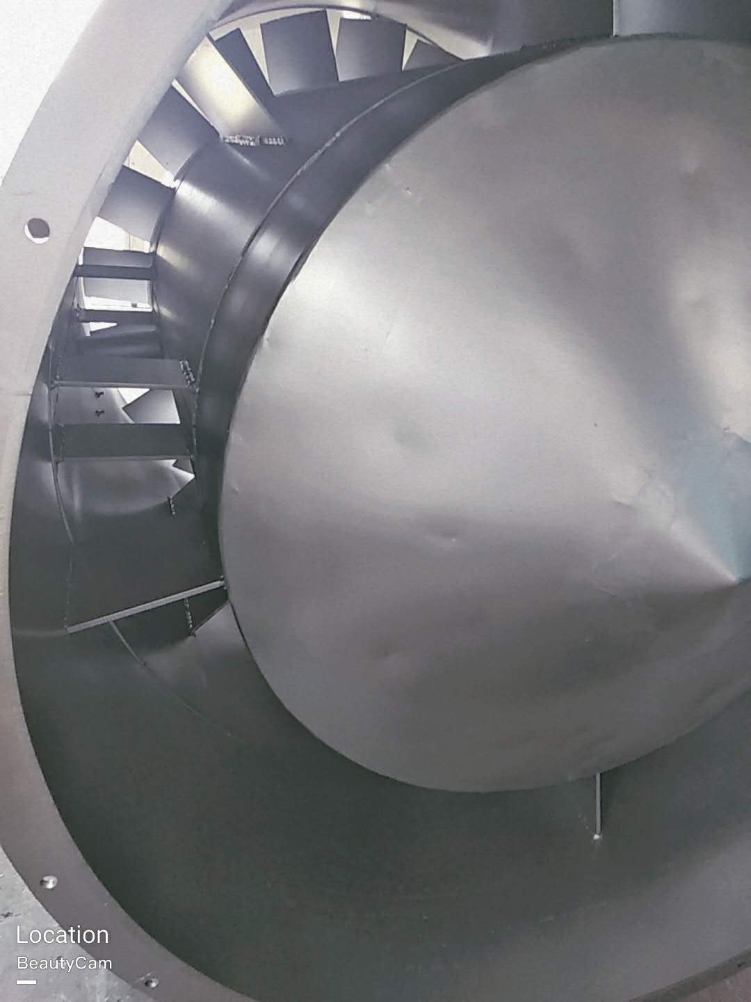
Correct maintenance is an important guarantee for the safe and reliable operation of the fan and the improvement of its service life. Therefore, Wet dedusting equipment manufactor When using fans, full attention must be paid. Impeller maintenance: at the initial stage of impeller operation and during all regular inspections, whenever there is an opportunity, the impeller must be checked for cracks, wear, dust and other defects. The impeller must be kept clean whenever possible, customized Wet dedusting equipment The steel wire brush shall be used regularly to remove the dust and rust on the impeller. As the travel time increases, the dust can not be evenly attached to the impeller, which will cause damage to the balance of the impeller and even cause rotor vibration. As long as the impeller is repaired, it needs to be dynamically balanced again. If possible, the portable trial dynamic balancing instrument can be used for on-site balancing. Before dynamic balancing, check whether all fastening bolts are tightened. Since the impeller has been operating in an unbalanced state for a period of time, these bolts may have become loose. Bearing maintenance: frequently check the oil supply of bearing lubricating oil. If the box leaks oil, tighten the bolts of the end cover a little. If this is not enough, you may have to use new sealing packing. When the bearing lubricating oil is in normal use, it should be replaced at least once every six months. When it is used for the first time, it should be done after 200 hours of operation. The second oil change should be done in 1 to 2 months. After that, the lubricating oil should be checked once a week. If the lubricating oil does not deteriorate, the oil change can be extended to 2 to 4 months. The specified brand of lubricating oil (specified on the general drawing) must be used when replacing, The old oil in the oil tank shall be completely drained and cleaned before new oil can be filled. If the fan bearing needs to be replaced, pay attention to the following matters: before installing the new bearing, the bearing and bearing box must be very clean. Place the bearing in the oil with a temperature of about 70~80 ℃ and heat it before installing it on the shaft. Do not force assembly to avoid damaging the shaft. Maintenance of other supporting equipment: see the respective user manual for the maintenance of various supporting equipment, including motors, electric actuators, instruments, meters, etc. These operating instructions are provided by each supporting manufacturer. The manufacturer will pack these instructions together and provide them to the user
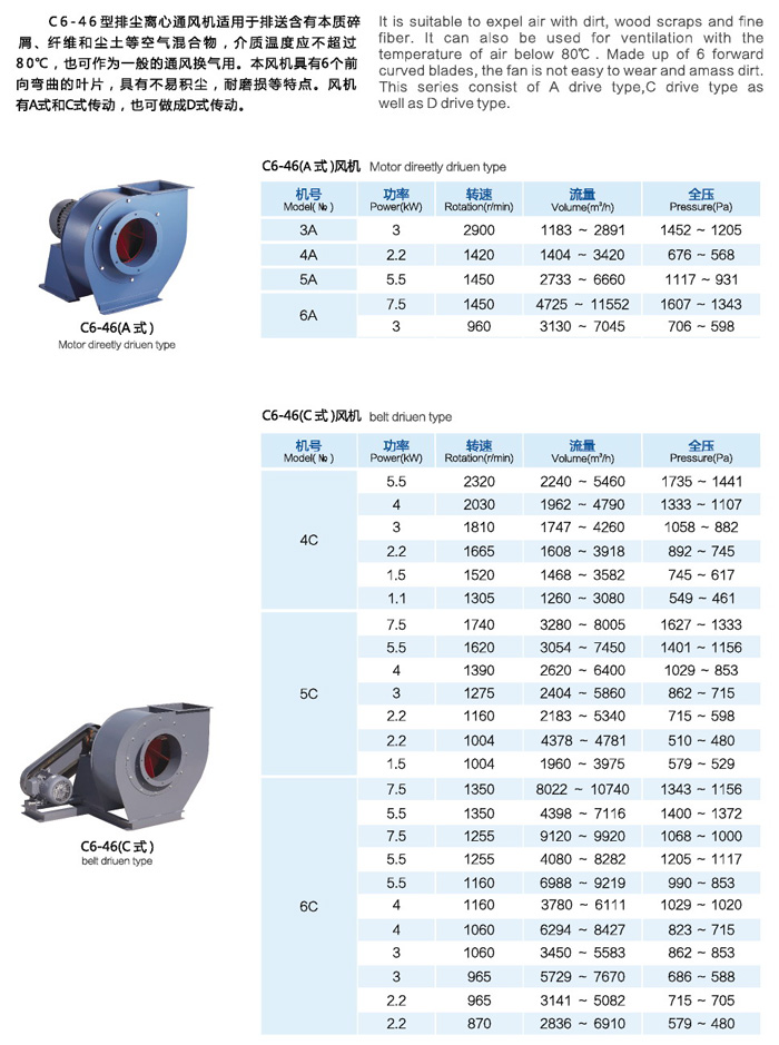
Selection and application of fan performance (I) Description of fan performance: 1. № 10, 12, 16, 20 are converted according to dimensionless performance of № 10 model. 2. № 5, 6, 8 are converted according to dimensionless performance of № 5 model. 3. № 5 and below shall be determined according to the performance of the measured prototype. Note: According to the dimensionless performance curve conversion formula, total pressure H=ρ u2 H (Pa) flow Q=900 π D22 uQ (m3/h) shaft power N=N × D22u3 ρ/4000 (kw), where D2 - impeller outer diameter (m) u - impeller outer edge linear speed (m/s) ρ - gas density (Kg/m3), the required power rate shall be based on shaft power plus mechanical loss and motor reserve. 4. The solid line is № 5 model, and the dotted line is № 10 model. The performance of the fan is expressed by the flow, total pressure, main shaft speed, shaft power, efficiency and other parameters of the fan, and there are certain relationships between the parameters, which are listed in the following table. The relationship of fan performance parameters changes density ρ, speed n changes speed n, atmospheric pressure P, gas temperature t Q1/Q2=n1/n2 H1/H2=(n1/n2) 2 ρ 1/ρ 2 N1/N2=(n1/n2) 3 ρ 1/ρ 2 η 1=η 2 Q1/Q2=n1/n2 H1/H2=(n1/n2) 2 (P1/P2) (273+t2/273+t1) N1/N2=(n1/n2) 3 (P1/P2) (273+t2/273+t1) η 1=η 2 Note: 1. In the middle, Q represents flow (m3/h), H represents total pressure (Pa), N represents shaft power (kw), η represents full pressure efficiency, ρ represents density (kg/m3), t represents temperature (℃), n represents speed (r/min), and P represents atmospheric pressure (Pa). 2. The footnote symbol 2 indicates the known performance and related parameters, and the footnote symbol 1 indicates the required performance and related parameters. (


